Once you have completed the steps from guide - CREATE A FIELD 1/2, you can proceed to adjust the operational settings for your robot.
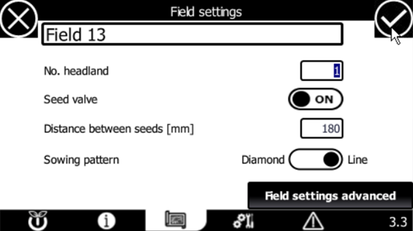
HMI PAGE 3.3 - FIELD SETTINGS
-
NO. HEADLANDS
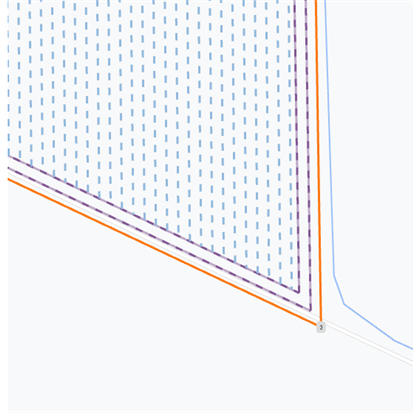
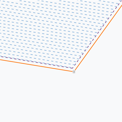
Set the number of headlands to define how many times the robot should drive around the field’s perimeter. This setting determines the width of the headland area, ensuring enough space is left between the field’s edge and the crop rows for tasks like turning harvesting machinery.
Refer to the images below for practical examples:
| NO. HEADLANDS: 6 | NO. HEADLANDS: 2 | NO. HEADLANDS: 1 |
 |
 |
 |
-
SEED VALVE
This setting is provided to you by FarmDroid as part of your seed test certification.
-
Seed valve ON: The seed valve will automatically open and close for optimal seeding accuracy. Use this setting when planting in portions, such as when the inter-row distance is greater than 3–4 cm.
-
Seed valve OFF: The seed valve remains open at all times. Use this setting only for very high-density seeding, such as when the inter-row distance is 2–3 cm.
-
-
DISTANCE BETWEEN SEEDS (MM)
Set the distance (in millimeters) between seeds within the same row.
NOTE 😀👍
To allow for inter-row weeding, the minimum distance between seeds must be at least 100 millimeters.
-
SOWING PATTERN
You can customize the sowing pattern according to the specific crop you are planting.


HMI PAGE 3.3 - FIELD SETTINGS ADVANCED
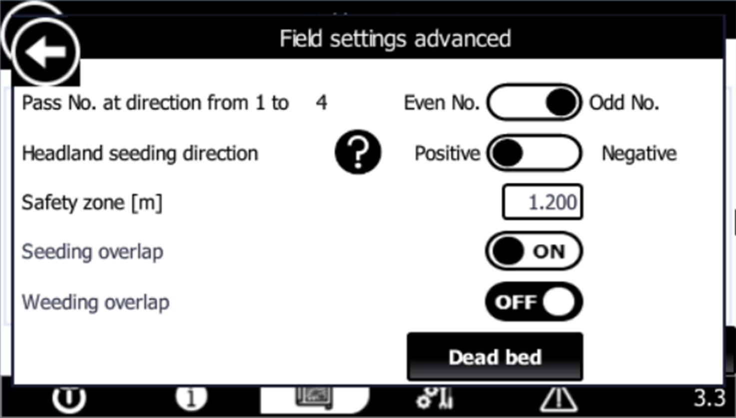
- PASS NO. AT DIRECTION FROM 1 TO (REFERENCE CORNER POINT)
Choose the desired direction for the robot’s first pass:- ODD – The robot’s first pass moves away from corner point 1 (standard setting).
-
- EVEN – The robot’s first pass moves toward corner point 1.
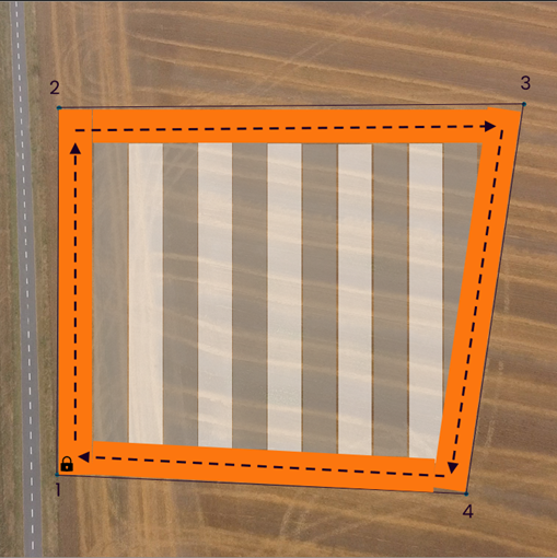
- The field has 4 corner points
- The reference line is set from CP1 to CP2
- The robot starts its operation from CP1


-
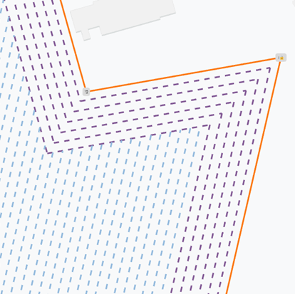
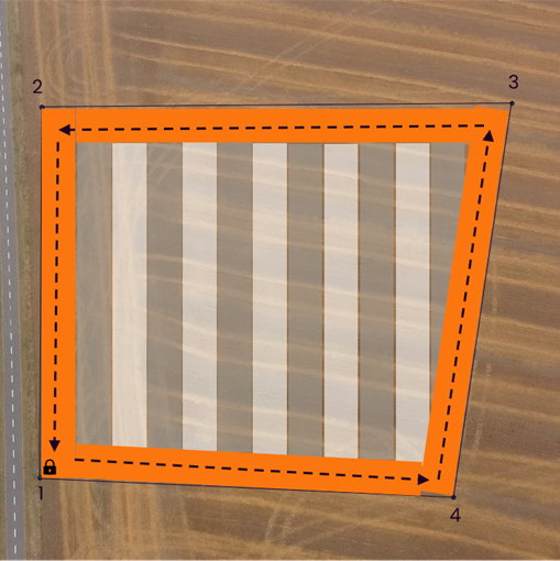
HEADLAND SEEDING DIRECTION
Choose the direction for robot operation in the headland:-
POSITIVE: The robot moves to the next corner point in ascending order.
-
NEGATIVE: The robot moves to the next corner point in descending order.
See the illustration below for clarification:
-
-
SAFETY ZONE
For more details, please see the dedicated article - Safety zone -
SEEDING AND WEEDING OVERLAP
For more details, please see the dedicated article - Seeding and weeding overlap
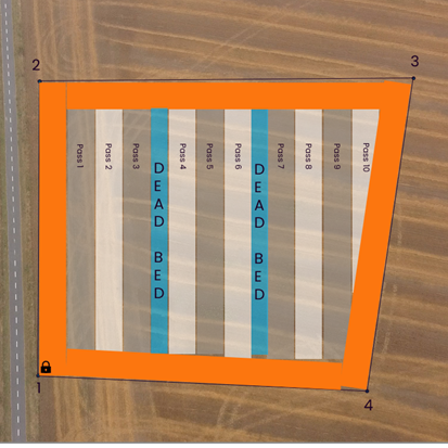
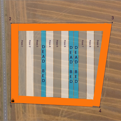
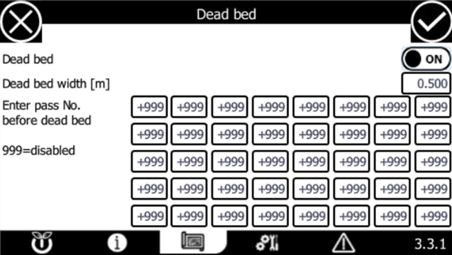
HMI PAGE 3.3.1 - DEAD BED
-
DEAD BED
Use this setting to enable or disable dead beds within the field.
-
DEAD BED WIDTH [M]
Enter the width of a single dead bed (in meters).
-
ENTER PASS NO. BEFORE DEAD BED
You can set up to 40 dead beds per field.
In the grid, enter the pass number that precedes each dead bed. To deactivate a specific dead bed, enter "999".For clarification, see the example below: