
Setting up a new field is straightforward when you follow each step carefully. Before beginning, be sure to:
-
Mount the droid on the field bracket to transport it across the field.
-
Confirm that the robot is receiving a FIXED RTK signal.
PROCEDURE
STEP 1
From the main HMI screen, swipe right to page 3 labelled "Field Setup."

STEP 2
Next, open the drop-down menu and choose an empty field slot.
WARNING ⚠️
If you select a slot that already contains a saved field (i.e., not empty), the existing field and all its settings will be permanently overwritten.

STEP 3
Tap on "Create new field."

STEP 4
Tap on the "?" icon, then enter the new field name as demonstrated in the example images below.


STEP 5
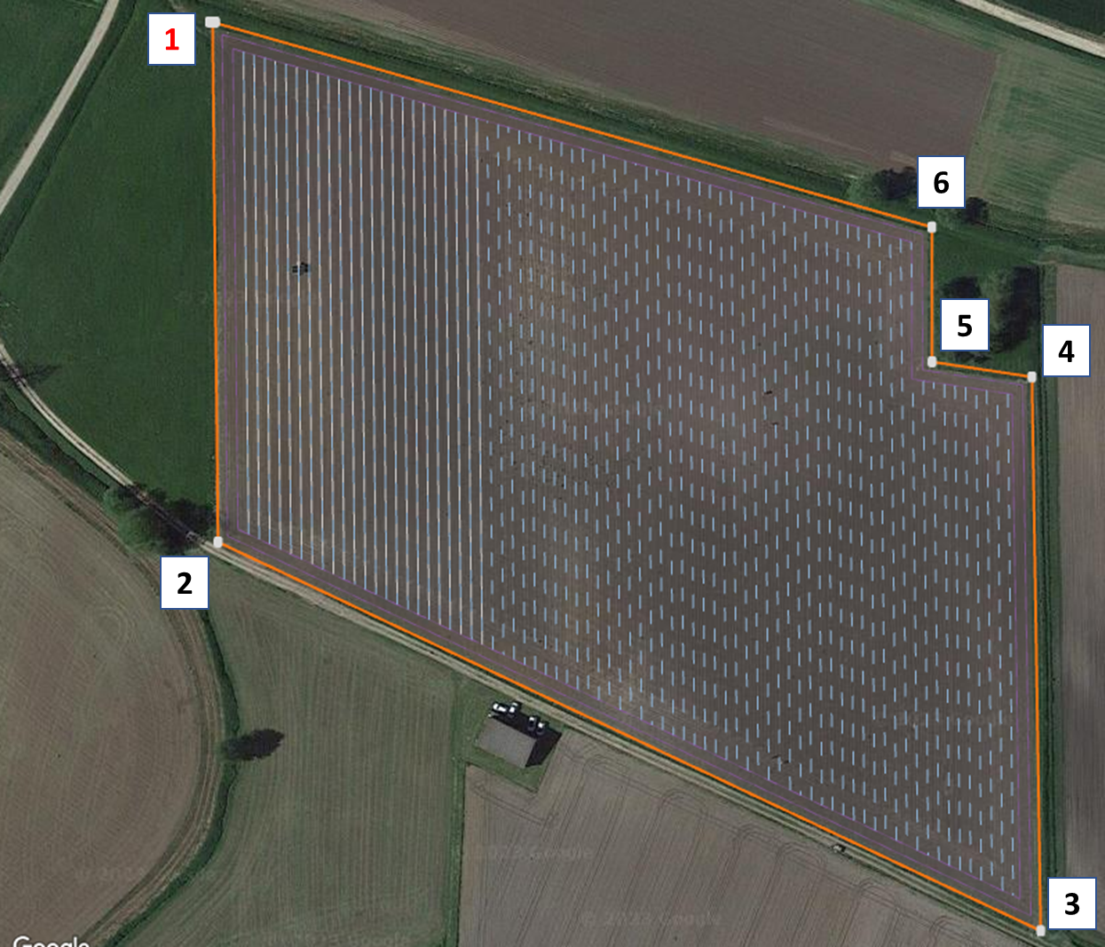
Move the robot to the first corner point of the field and save its location.
TIPS AND TRICKS 😁👇
Keep in mind that the location being saved corresponds to the position of the Front GPS Antenna.

TIPS AND TRICKS 🤓👍
We highly recommend saving corner point 1 at the point on the field nearest to the main access area—such as a gate or the entrance from the road where you deliver the droid—since the position of corner point 1 cannot be changed after it is saved.STEP 6
After saving corner point 1, you have two options:
- If you are satisfied with its position, proceed to move the robot to the remaining corner points and save each one until the field is fully outlined.
- If you want to adjust corner point 1, press "Undo last corner point" and save the new position when the robot is correctly placed.
Note: The "Undo last corner point" button is available each time you save a corner point.

STEP 7
Continue outlining the field by moving the droid to each desired corner and saving each point, until the entire field perimeter is complete.
STEP 8
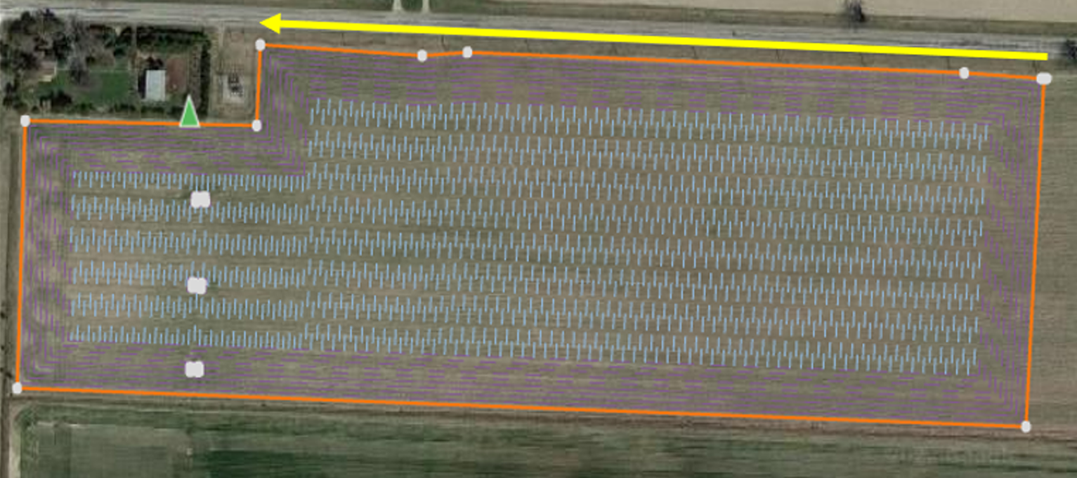
After saving all the corner points, set the reference line—the main AB line that determines the robot’s driving direction.
The reference line always begins at corner point 1, but you can choose which corner it points to.
To define it, tap on the "0" slot and enter the number of the desired corner point for the line’s direction.

TIPS AND TRICKS 😁👇
When setting the reference line, aim for a configuration that minimizes the number of turns required.For example, if you set the reference line between corner point 1 and corner point 2, all field rows will be parallel to this line.
Problems can occur if the reference line is set using the wrong corner point, as shown below:
STEP 9
After setting the reference line (for example, from CP1 to CP4 as shown), you can proceed by pressing the arrow in the top-right corner.

STEP 10
Review the field details to verify:
-
The number of corner points defining the field boundary
-
The current reference point for the AB lines
If everything is correct, tap on "Save" to continue. If you need to make changes, tap the arrow in the top-left corner to return to the previous page.

STEP 11
If your field contains obstacles within its perimeter—such as electricity poles, wells, or water outlets—select "Set obstacles" to begin mapping them.
NOTE 😉
Each obstacle requires at least 3 corner points to be mapped correctly.
The procedure for mapping obstacles is the same as setting up the field: move the droid to each point and save the position.
After mapping an obstacle, you can either continue adding more obstacles or finish the field setup by clicking the arrow in the top-right corner.

STEP 12
With the field boundary and any obstacles now set, proceed to the next guide to configure the robot's operational settings for this field - CREATE A FIELD 2/2