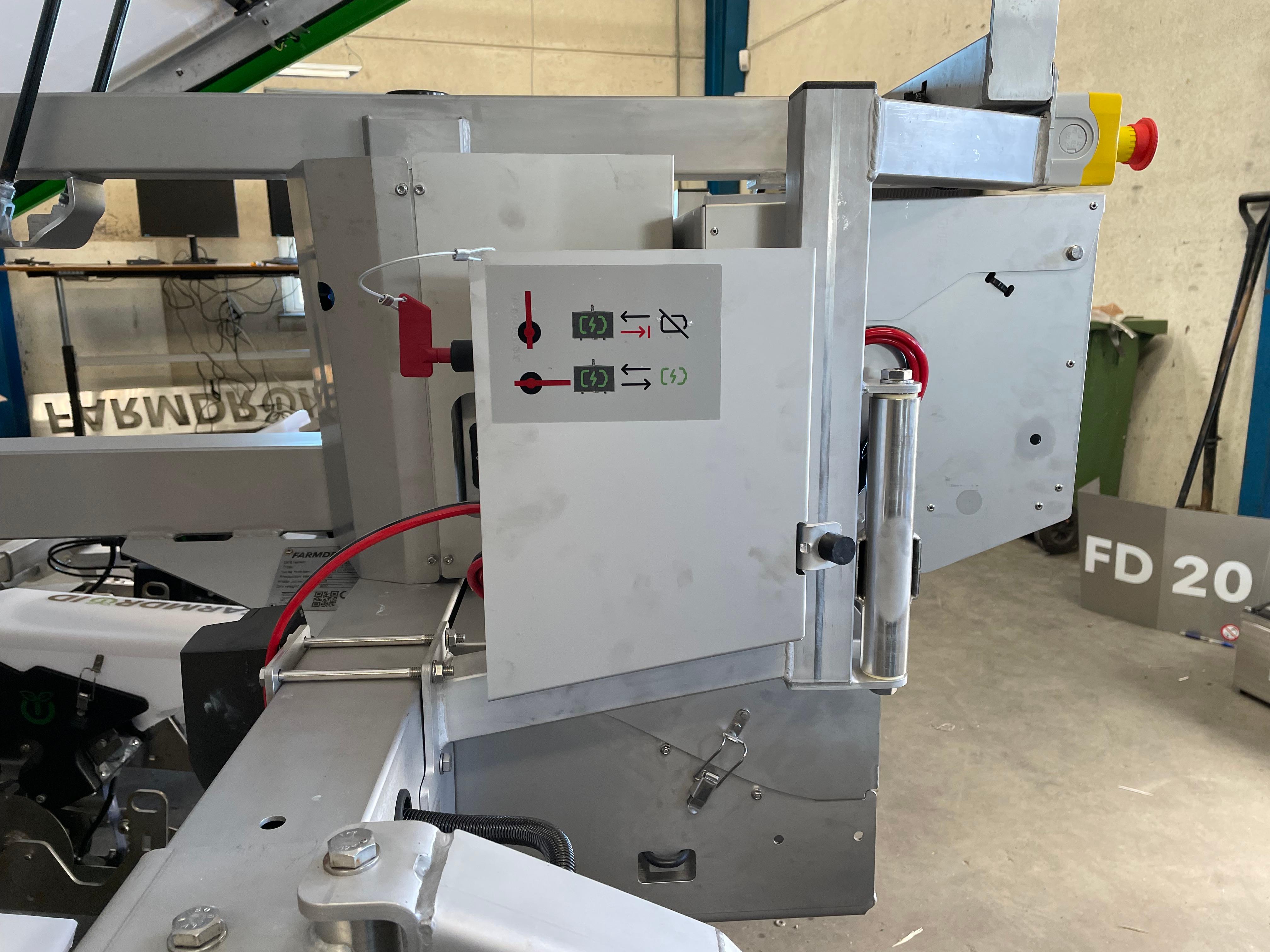
POWER BANK (2/3): mechanical assembly
Step by step guide for the MECHANICAL assembly of the power bank add-on
NOTE 😀👍
This guideline has been updated to fix the latest mechanical changes for item 109010019R01 POWER BANK KIT - RETROFIT
BEFORE STARTING, REMEMBER TO CUT OFF ANY POWER FROM THE MAIN SWITCH, AS WELL FROM THE SOLAR PANELS!
The tools needed for the installation are:
- 19 mm wrench
- 17 mm wrench
- 13 mm wrench
- 10 mm wrench
- 3 mm Allen key
- 6 mm Allen key
- flat head or Phillips screwdriver
1) Start by removing the existing battery cover
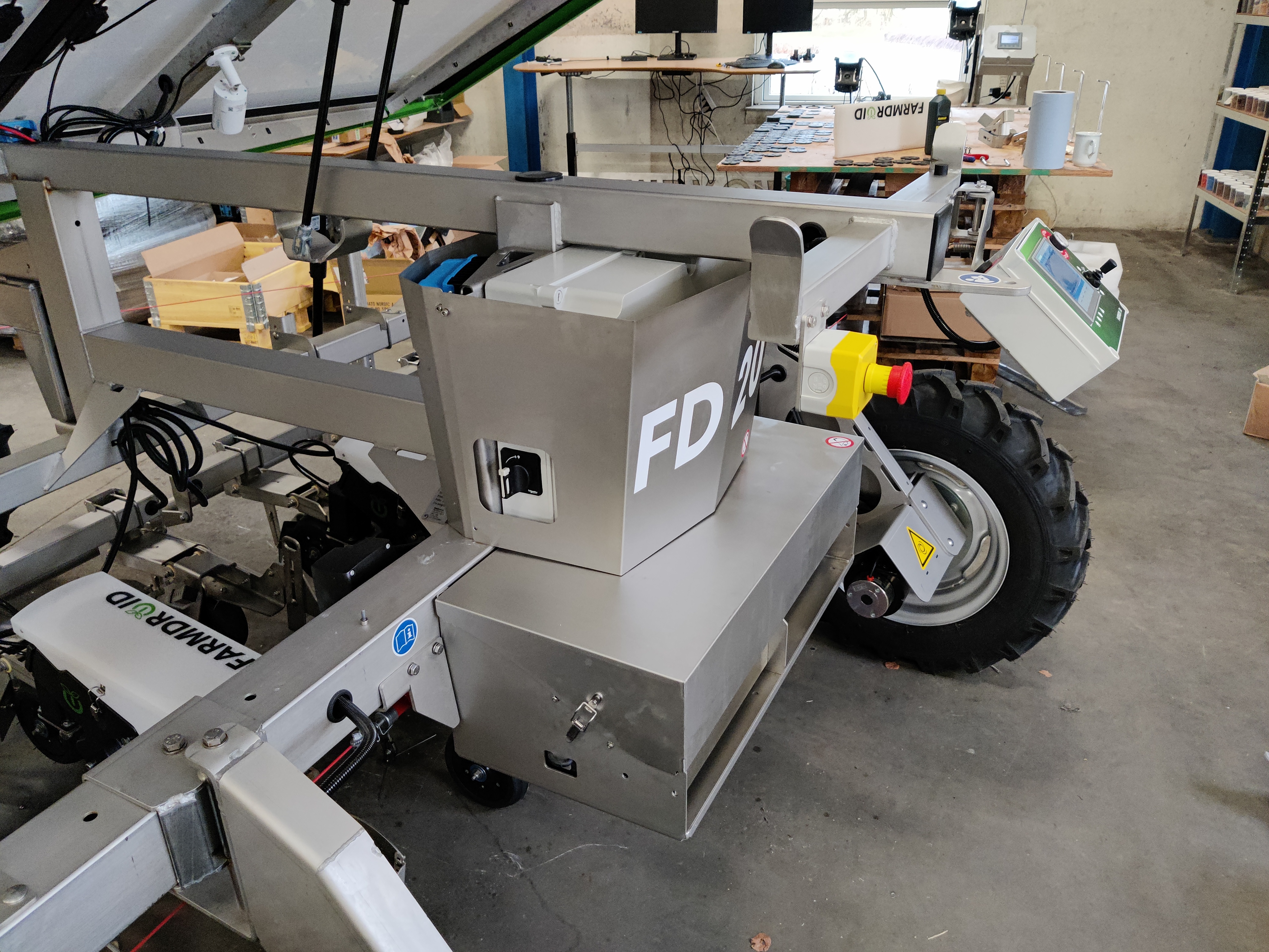
2) Remove, on both sides of the robot, the old lifting supports with a 13 mm wrench
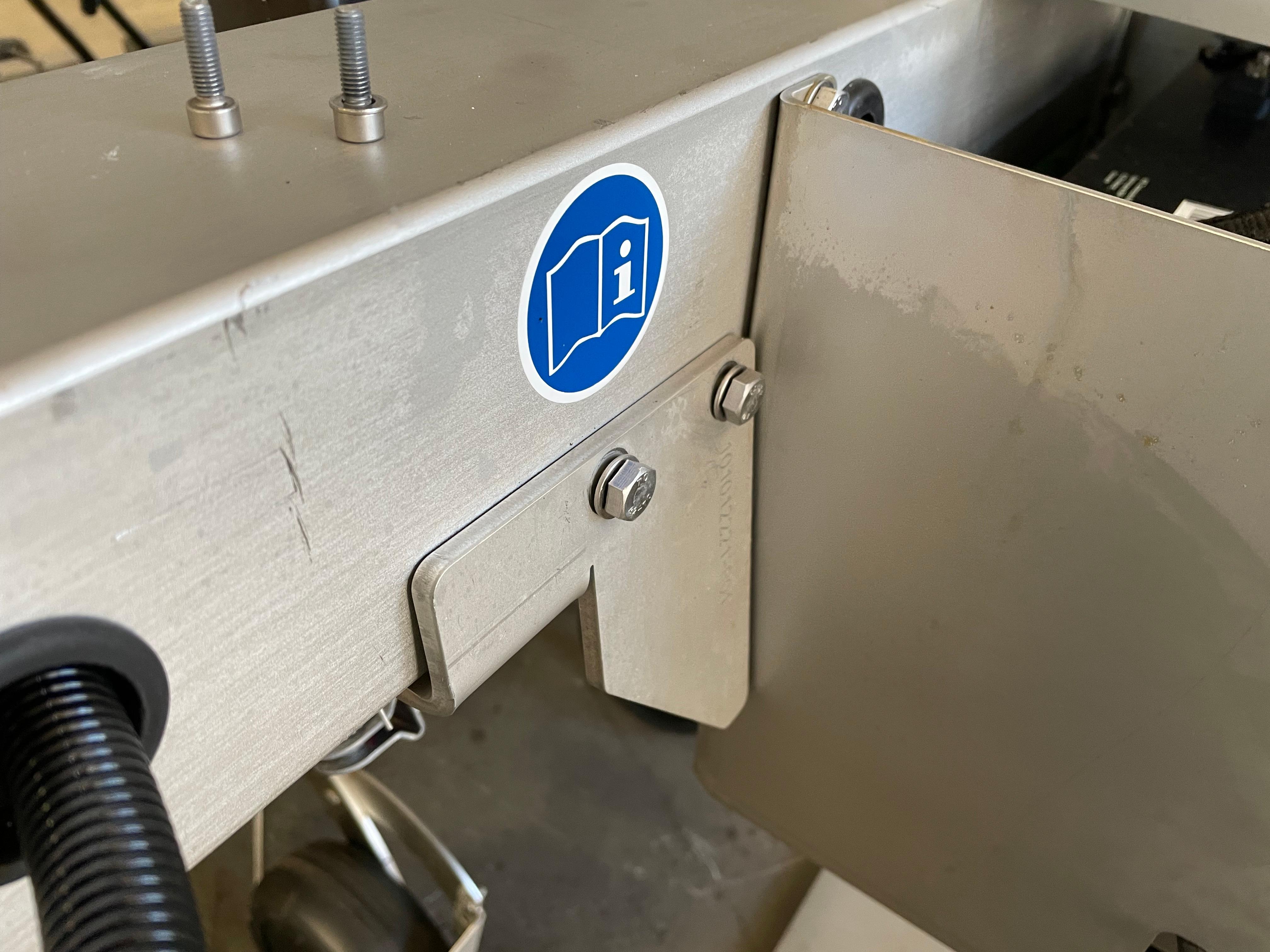
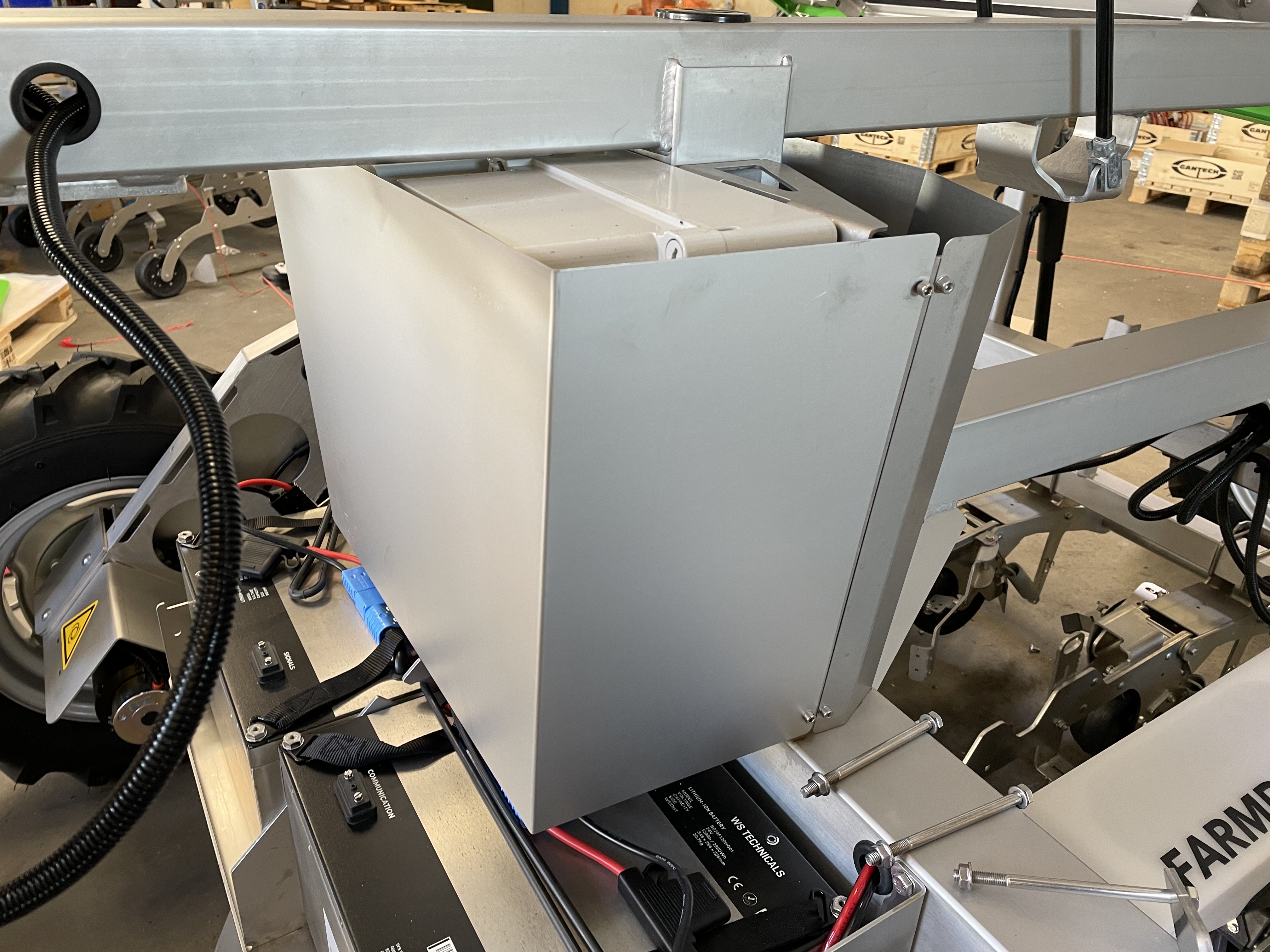
3) Remove the old electrical panel cover and replace with the new cover provided in the kit
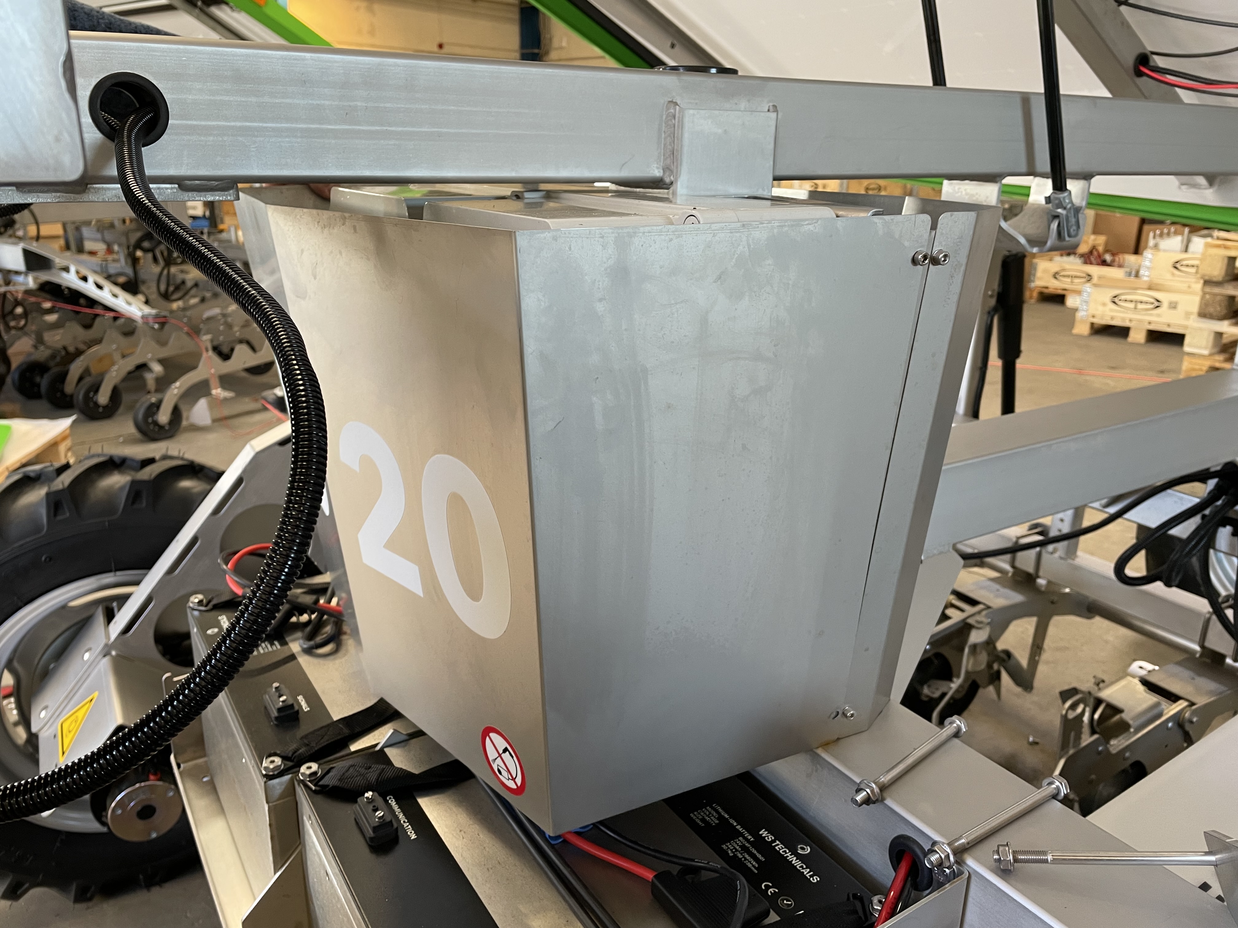
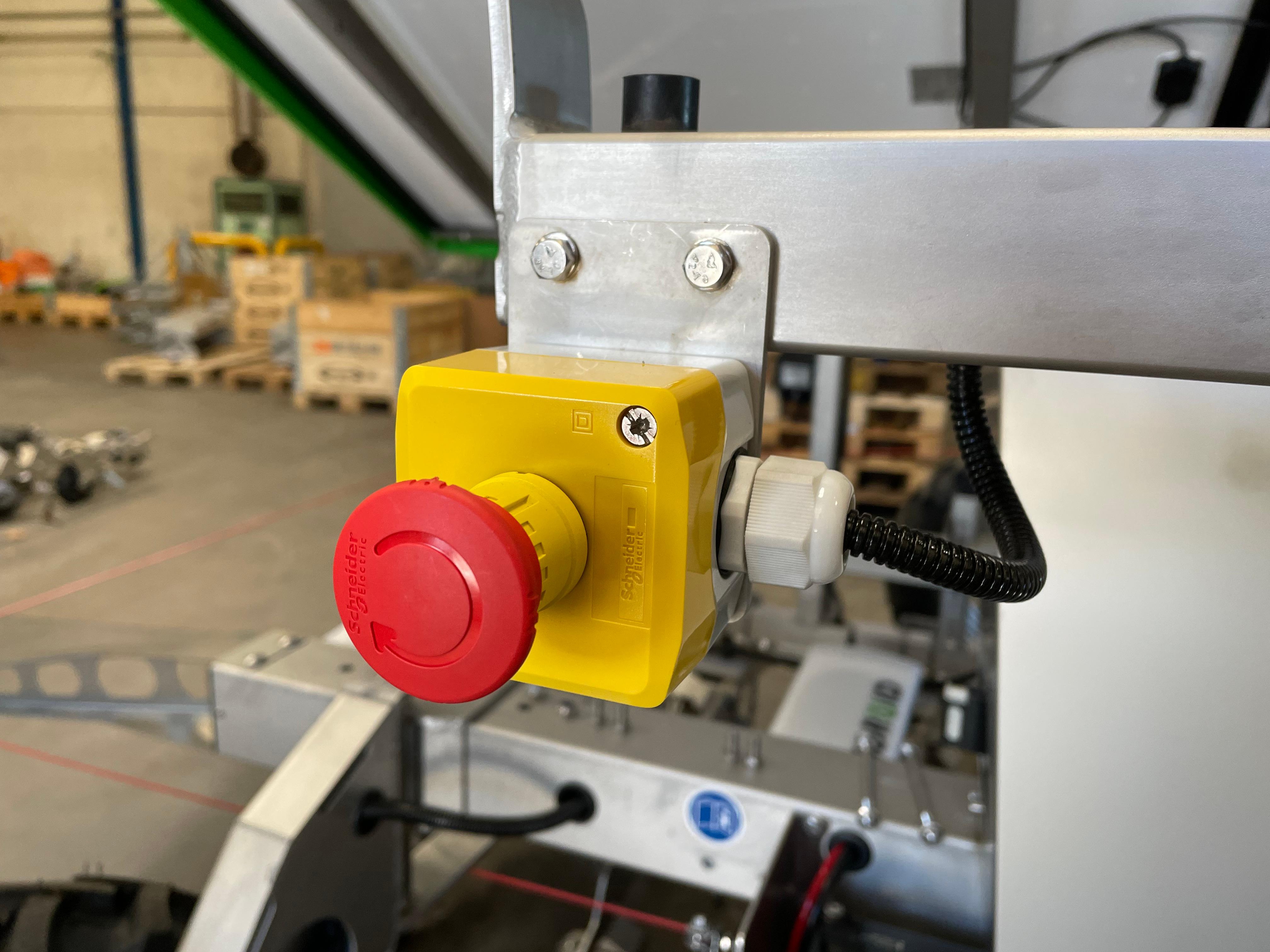
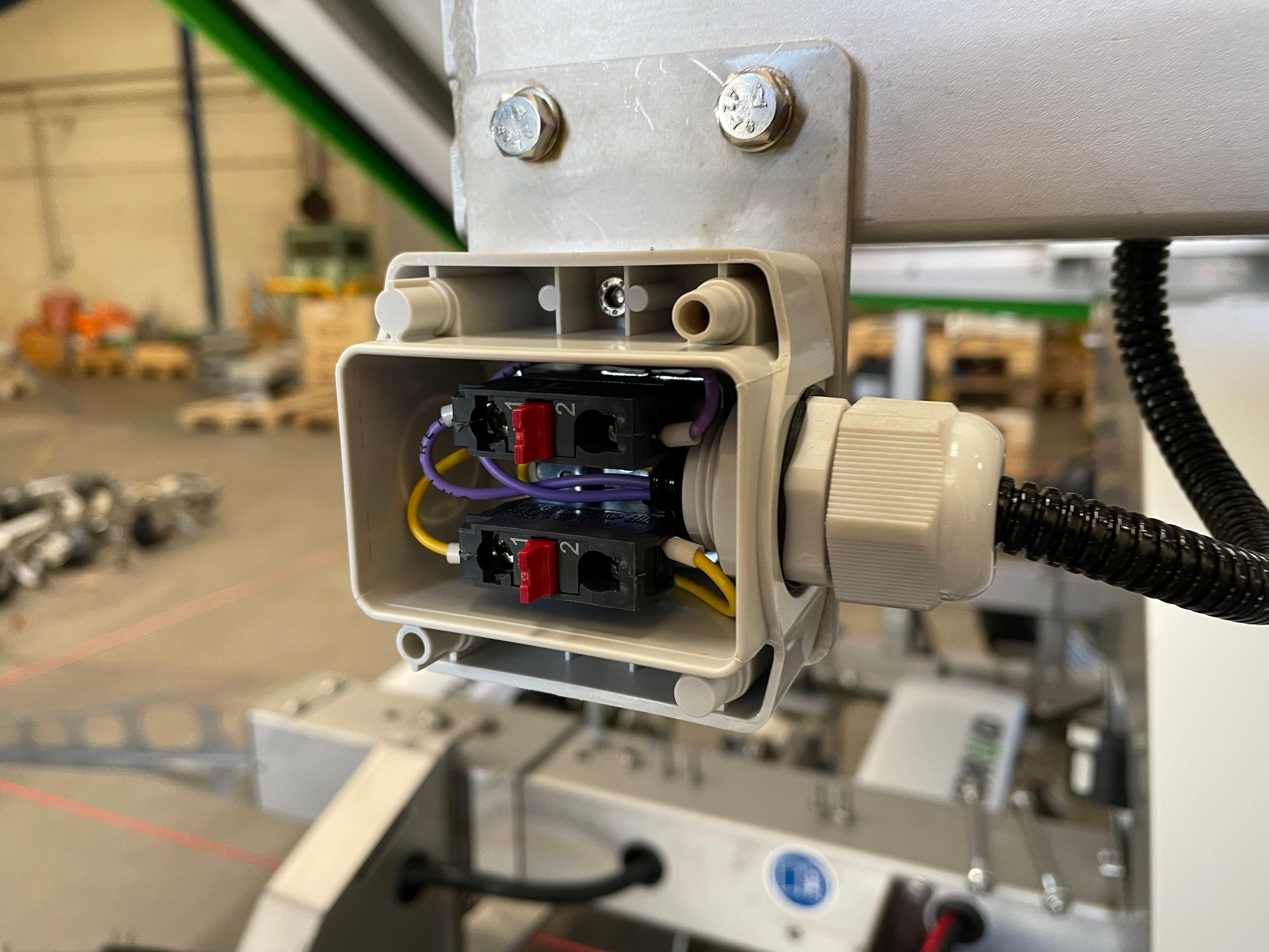
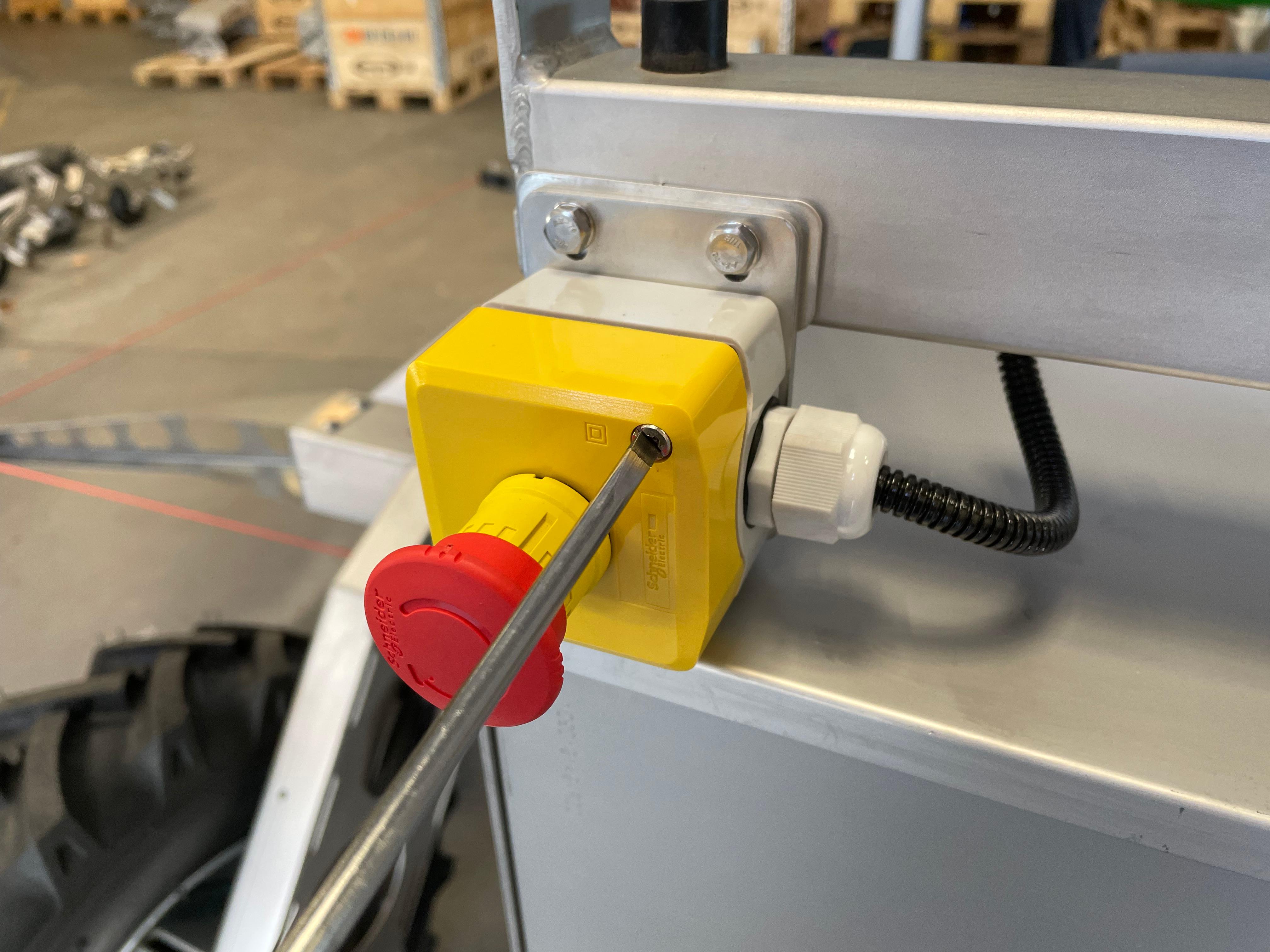
4) Remove the emergency stop by using a screwdriver and a 3mm Allen key
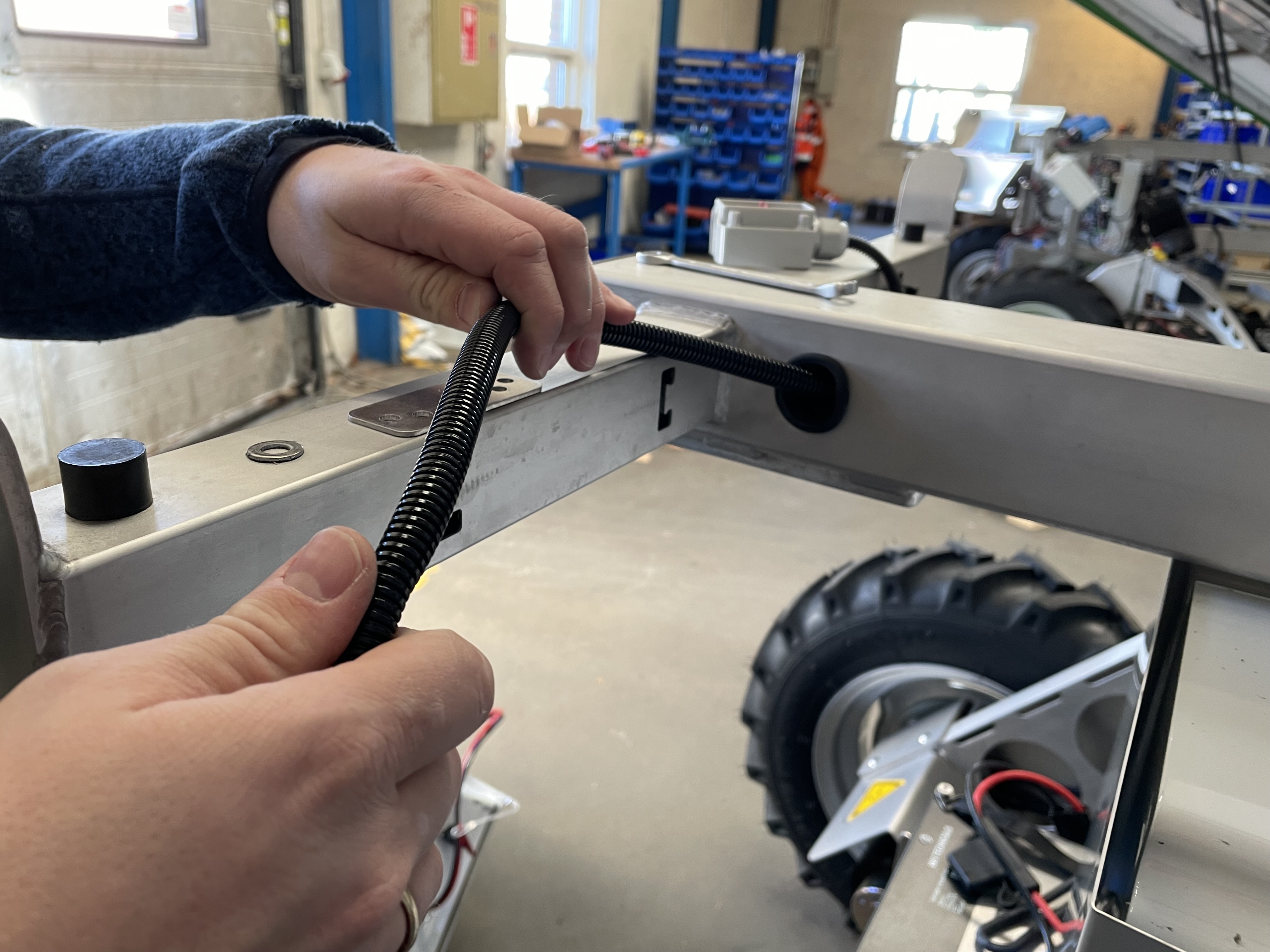
5) In the right side of the robot, cut the zip ties and pull about 15 cm of the cable running to the HMI, fix the extended wire with two zip ties
6) Remove the HMI support bracket from the frame, using a 10 mm wrench, then place the HMI on the frame, for now
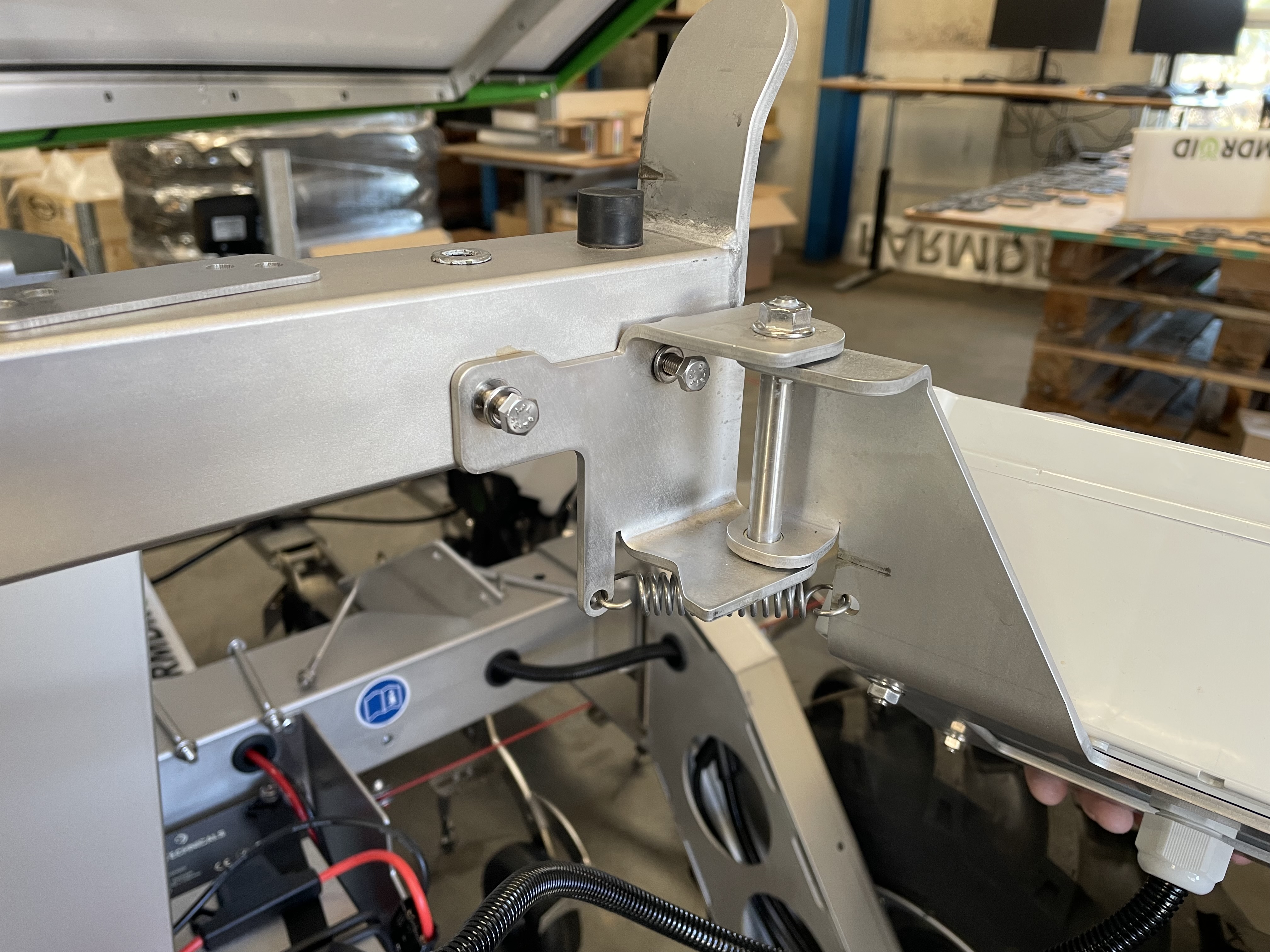
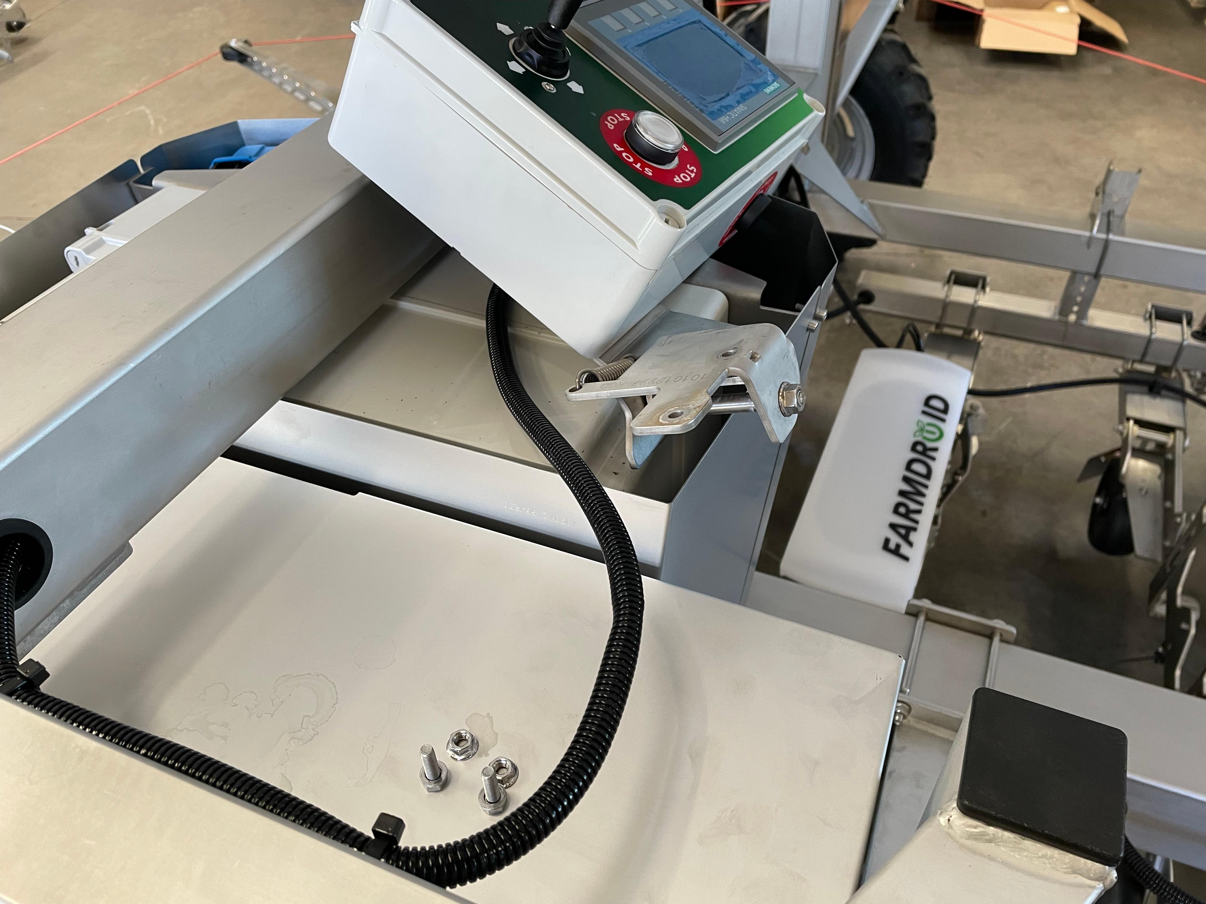
7) Secure the power-bank side support bracket to the upper part of the frame.
NOTE: you may need help from another person to hold the bracket in place.
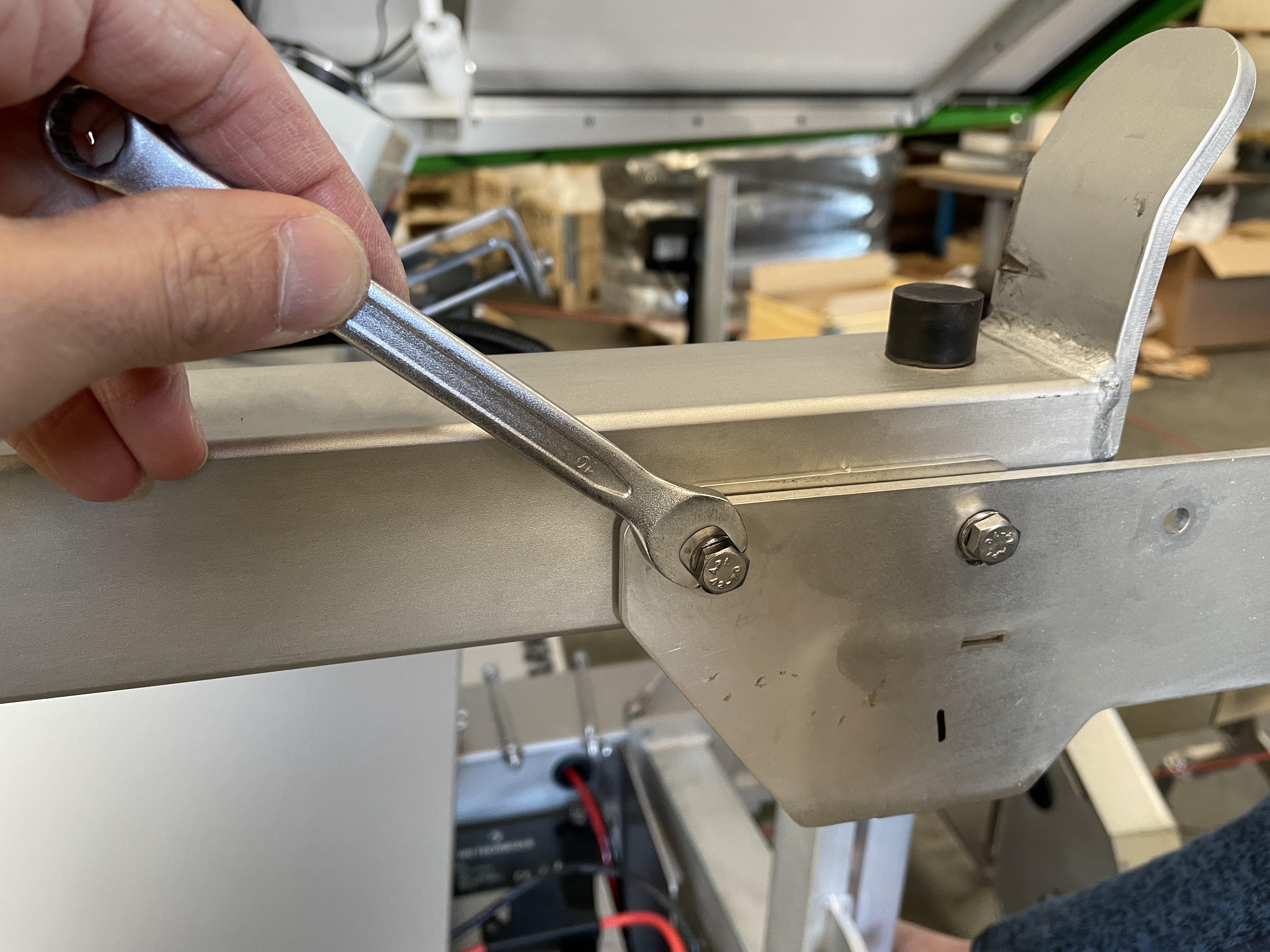
8) Now secure the lower part of the bracket to the robot frame
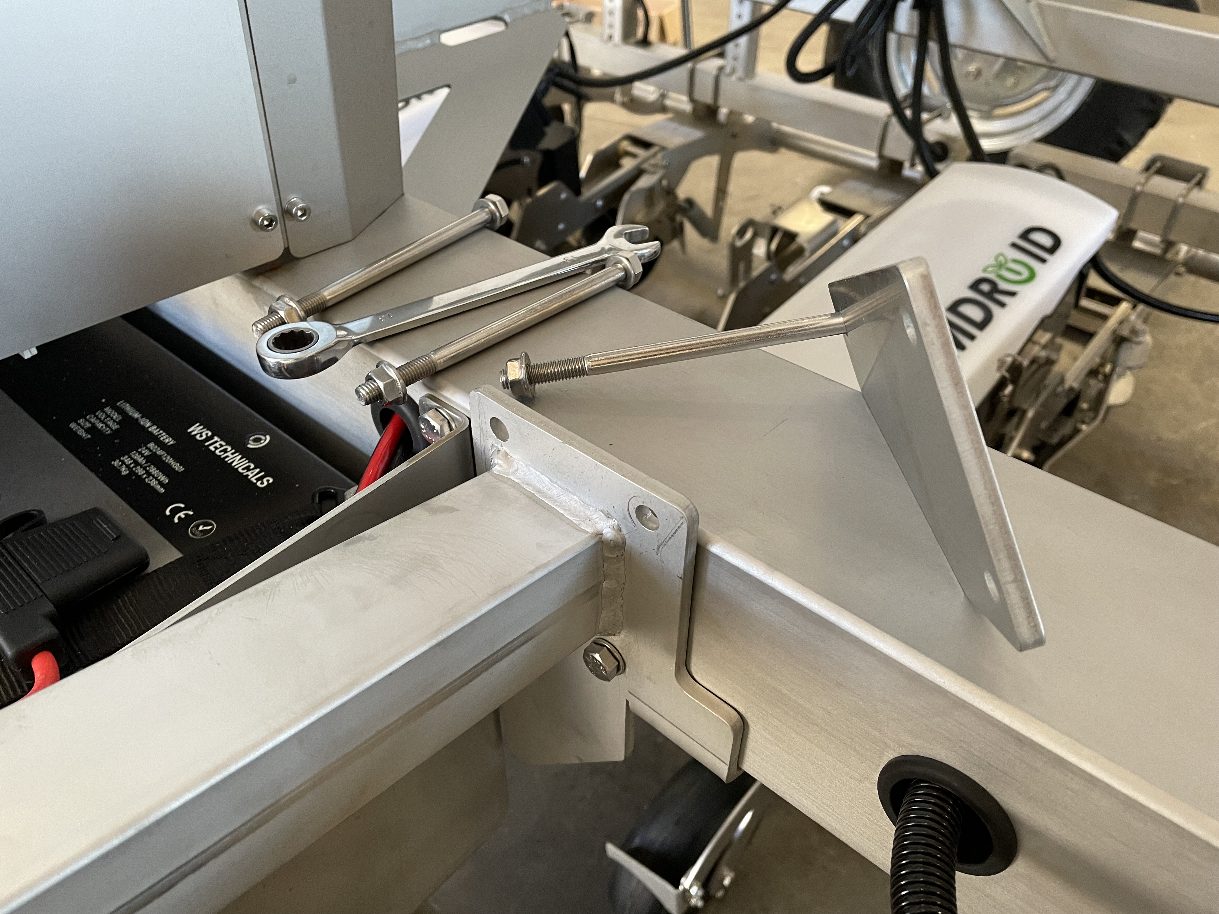
9) Secure all 5 screws
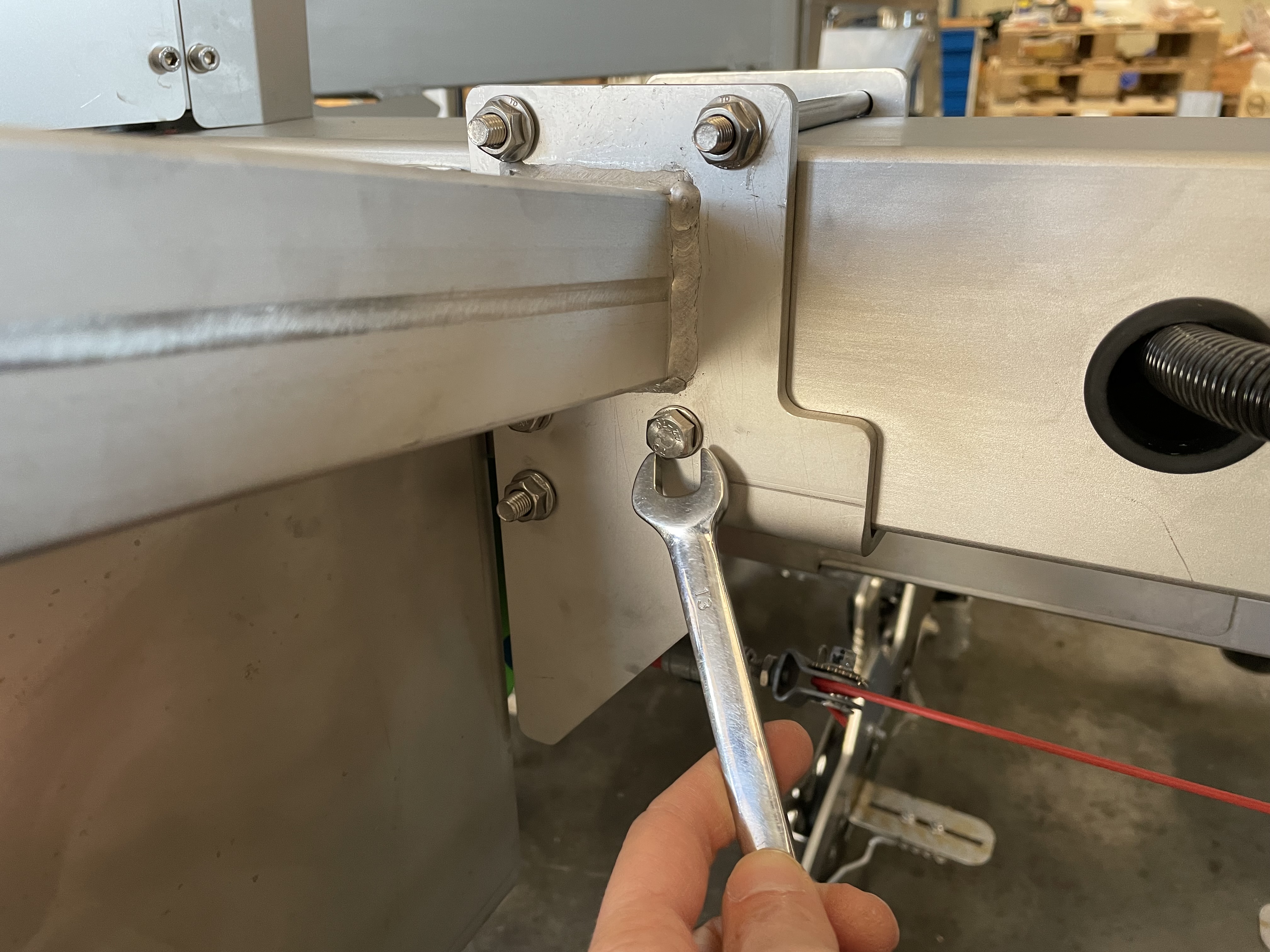
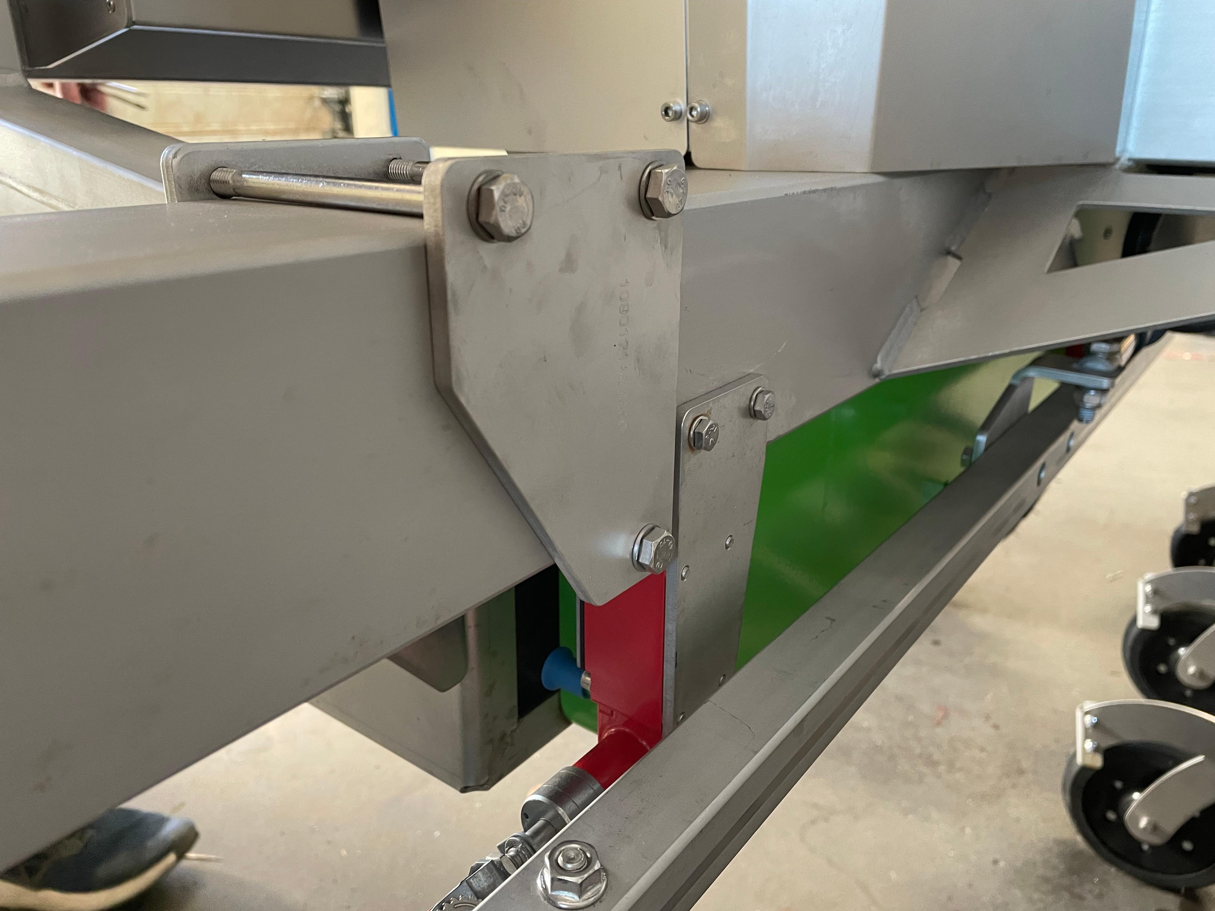
10) Have a person to hold the power bank assembly in place, then tighten the two screws which secure the assembly to the top part of the robot's frame
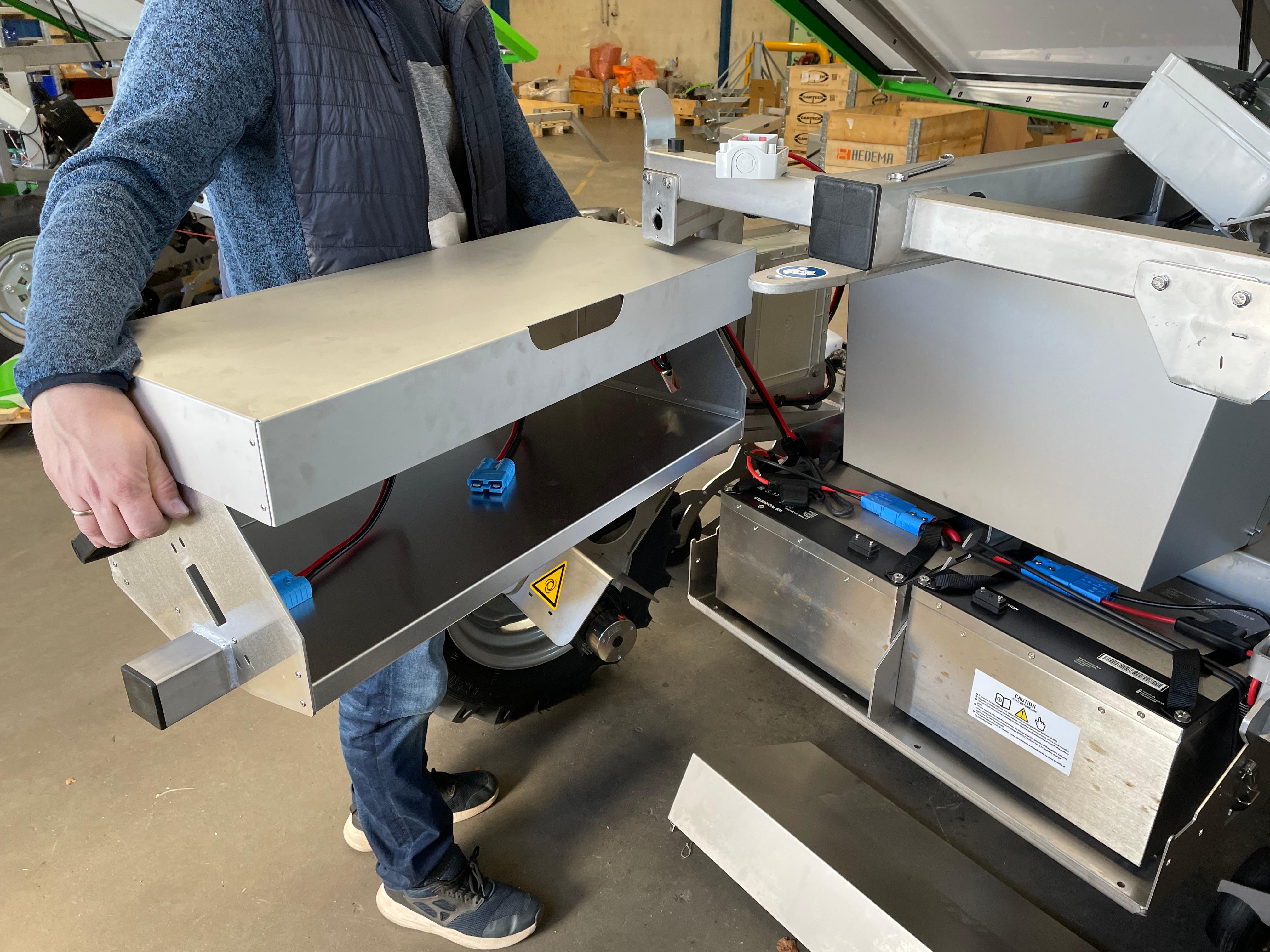
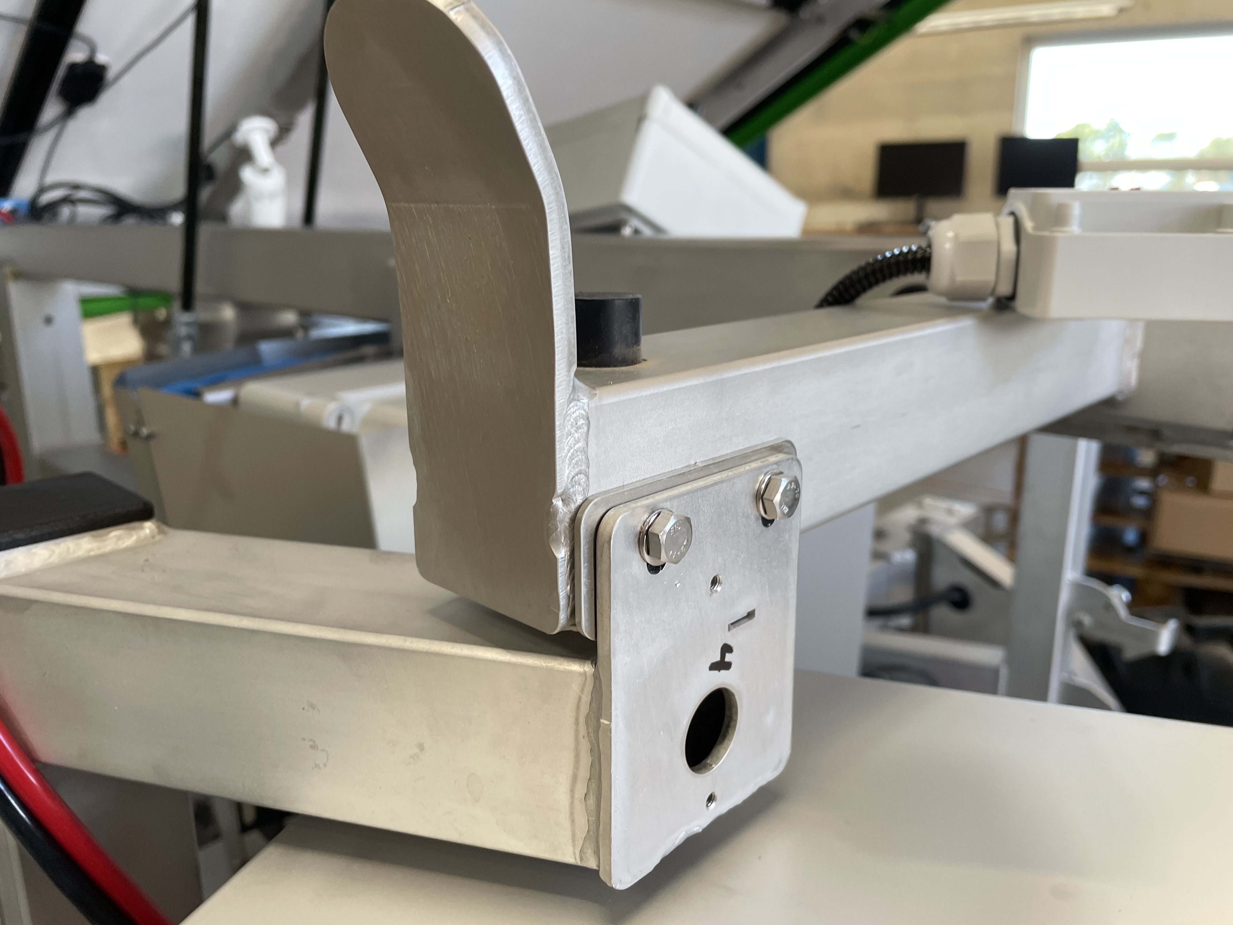
11) Correct placement of the lower side of the support
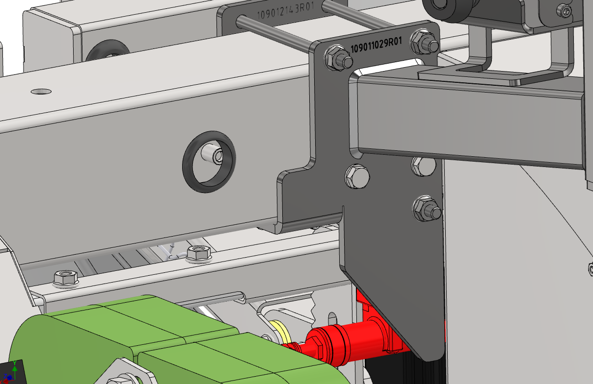
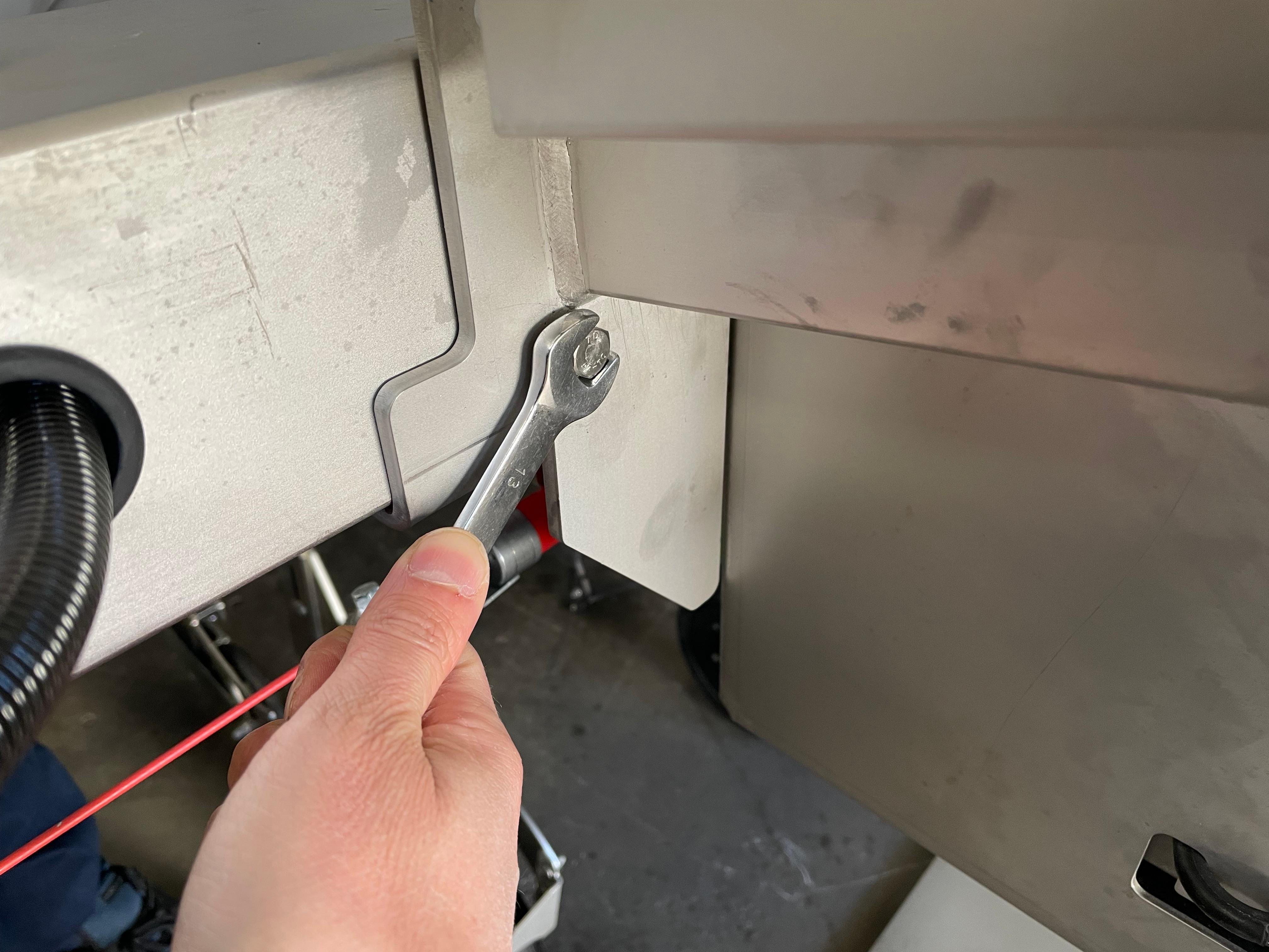
12) Secure the screws and nuts in place with a 13 mm wrench
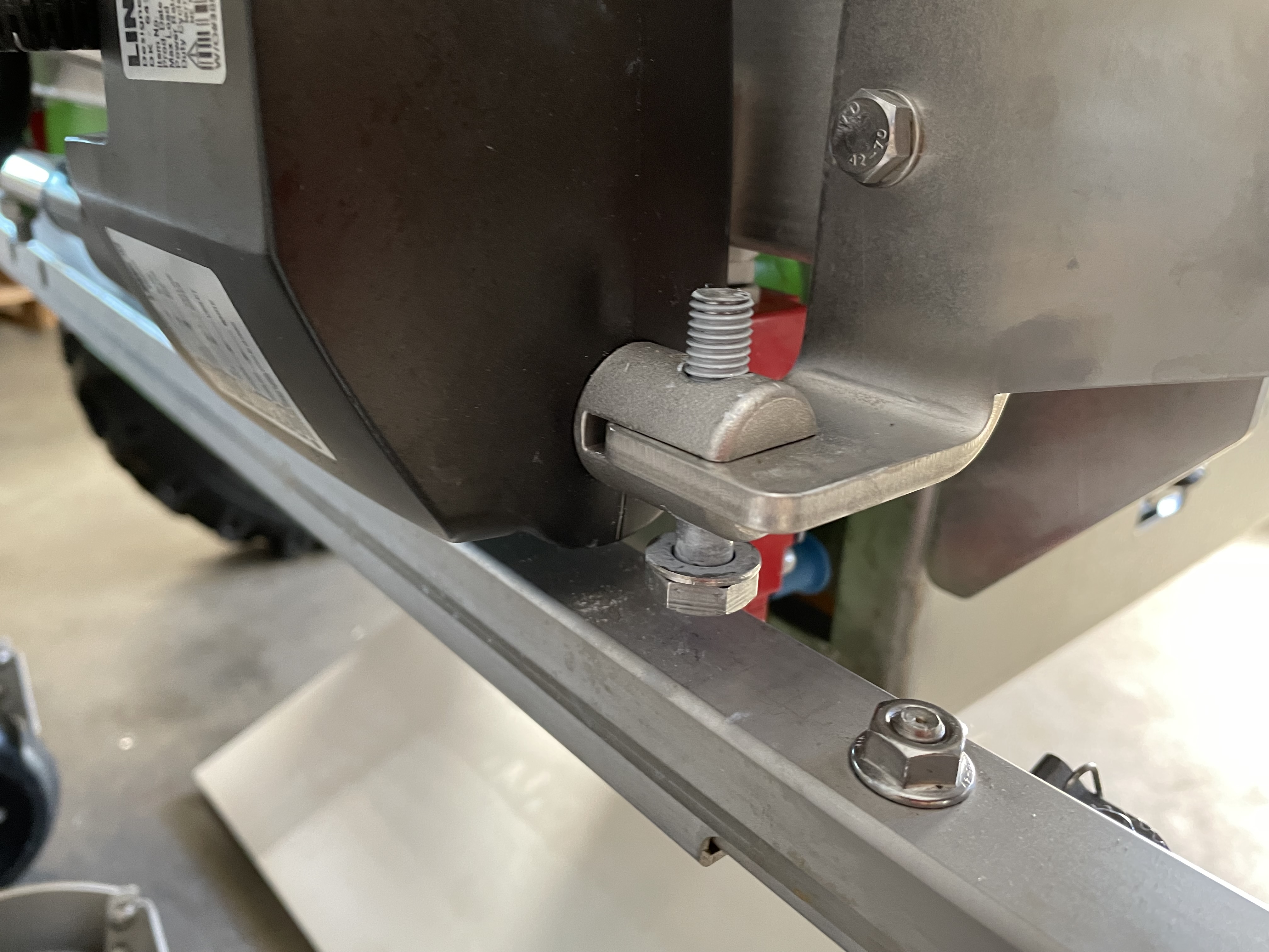
13) Secure the actuator to the frame with the new bracket. Tighten the nuts.
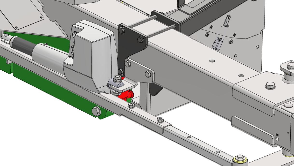
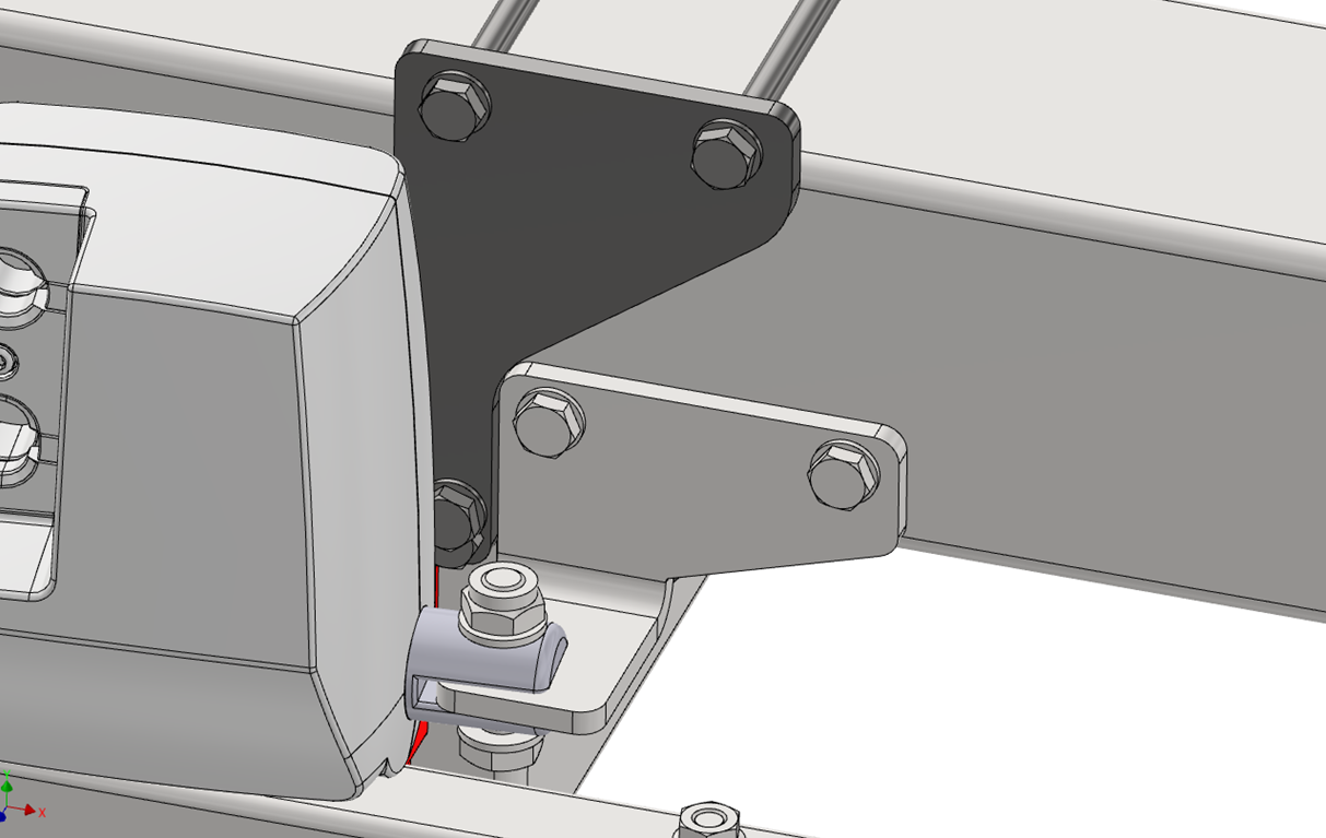
14) Secure the left-side bracket of the power bank to the frame, using 5 screws. Make sure to tighten the nuts.
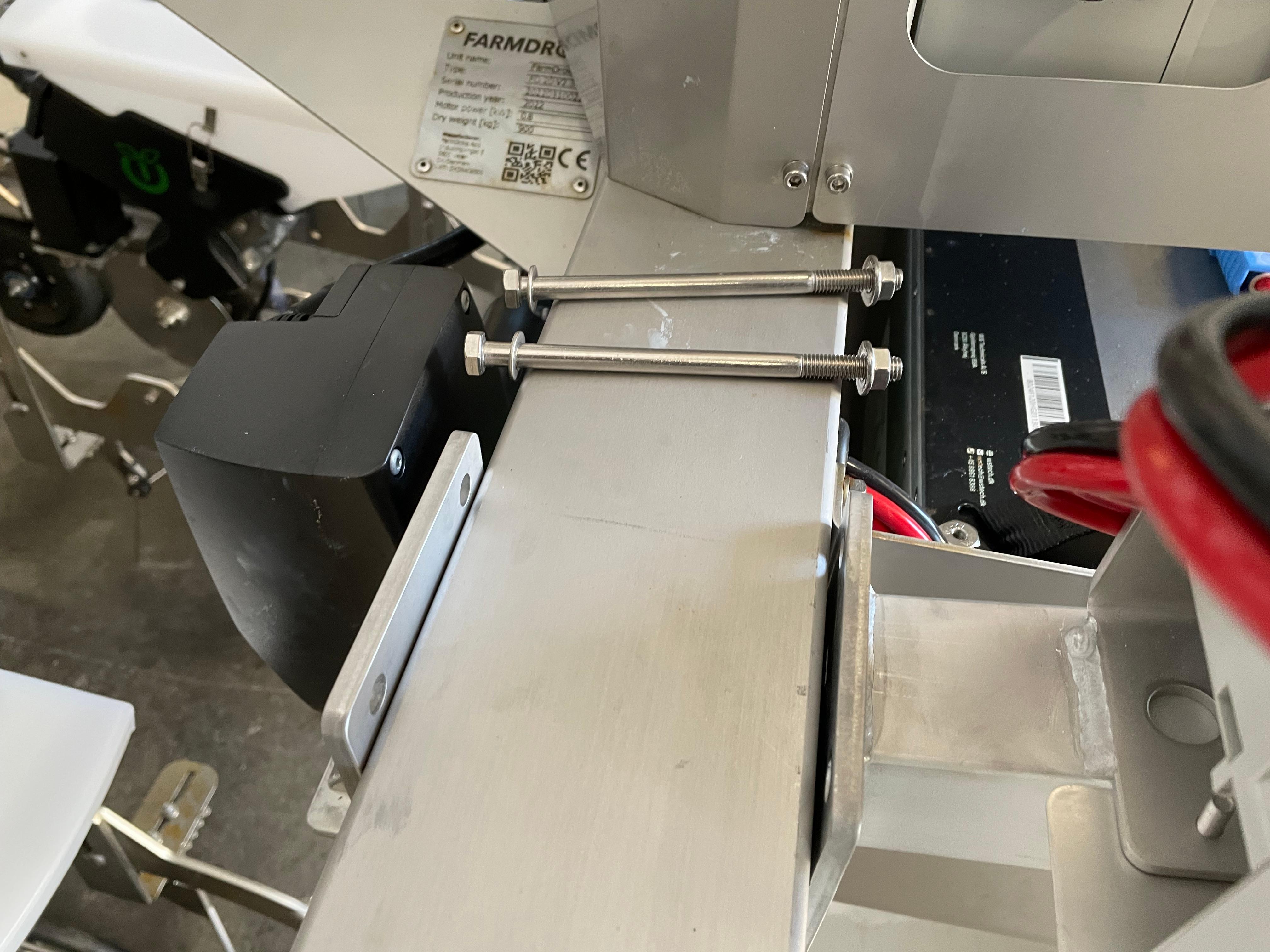
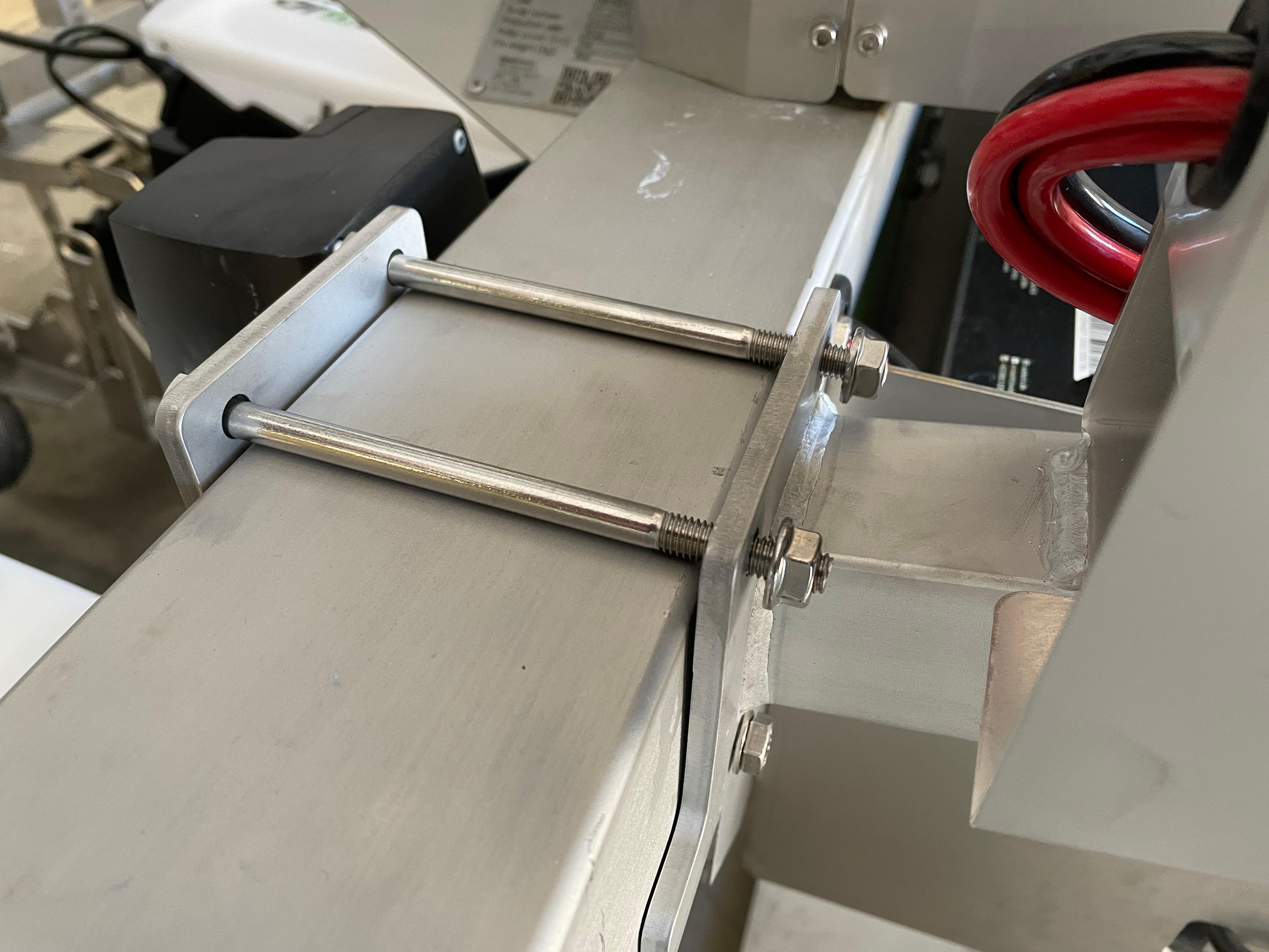
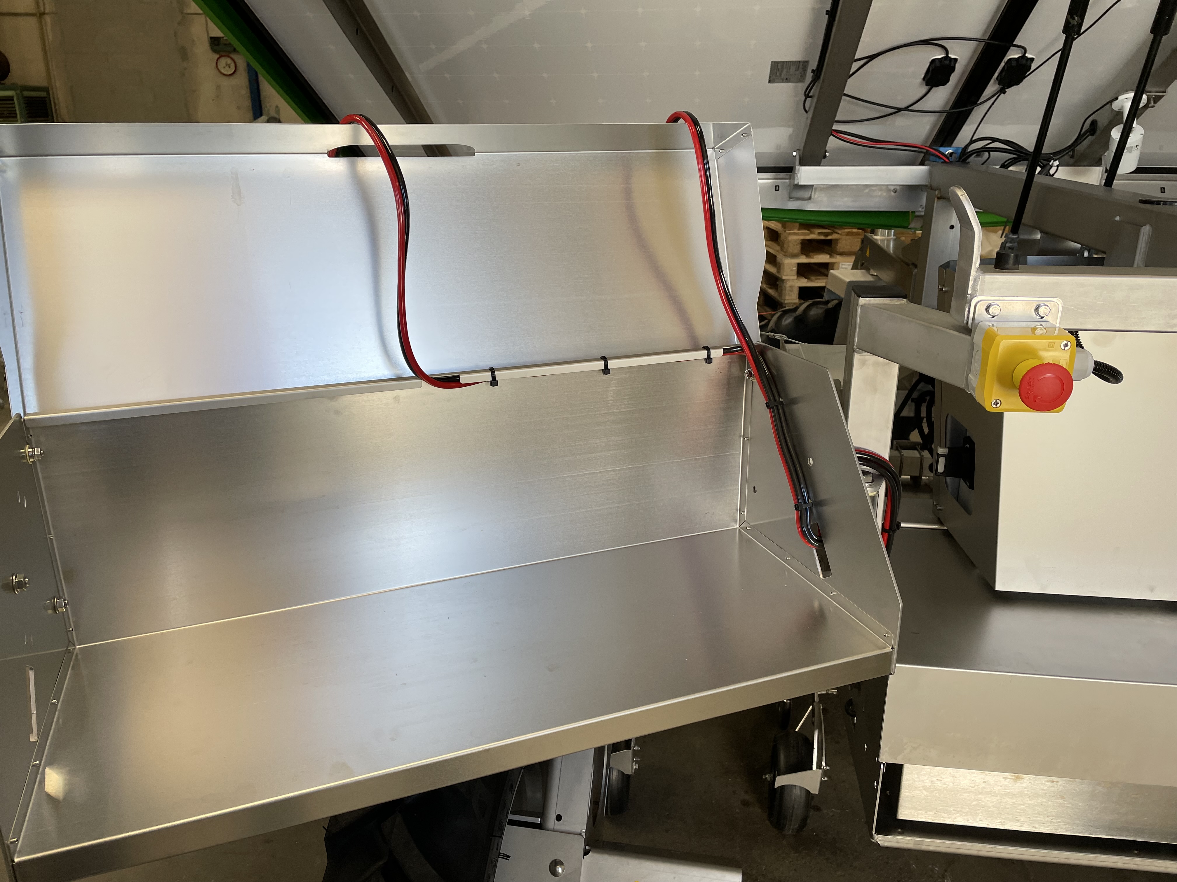
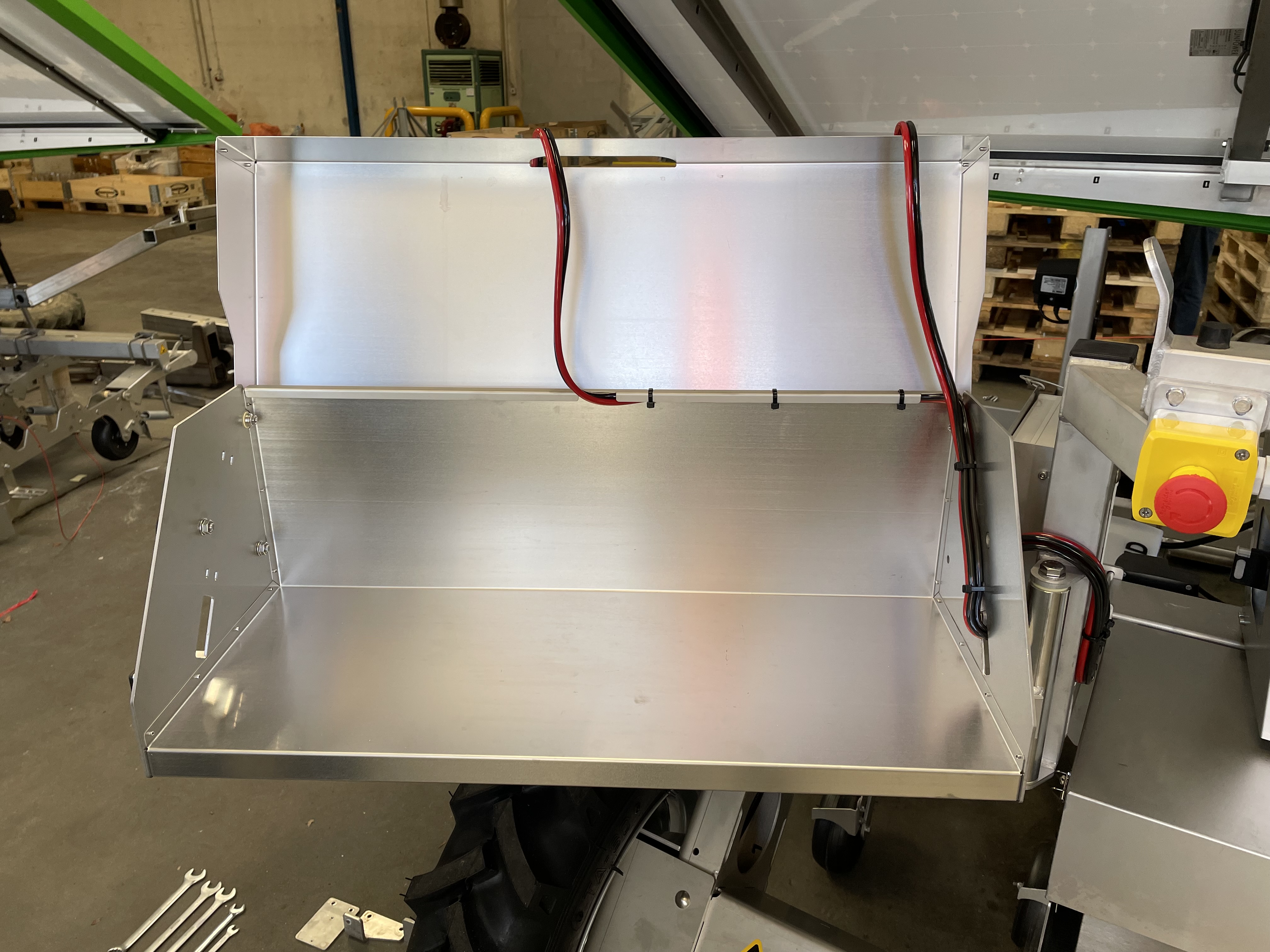
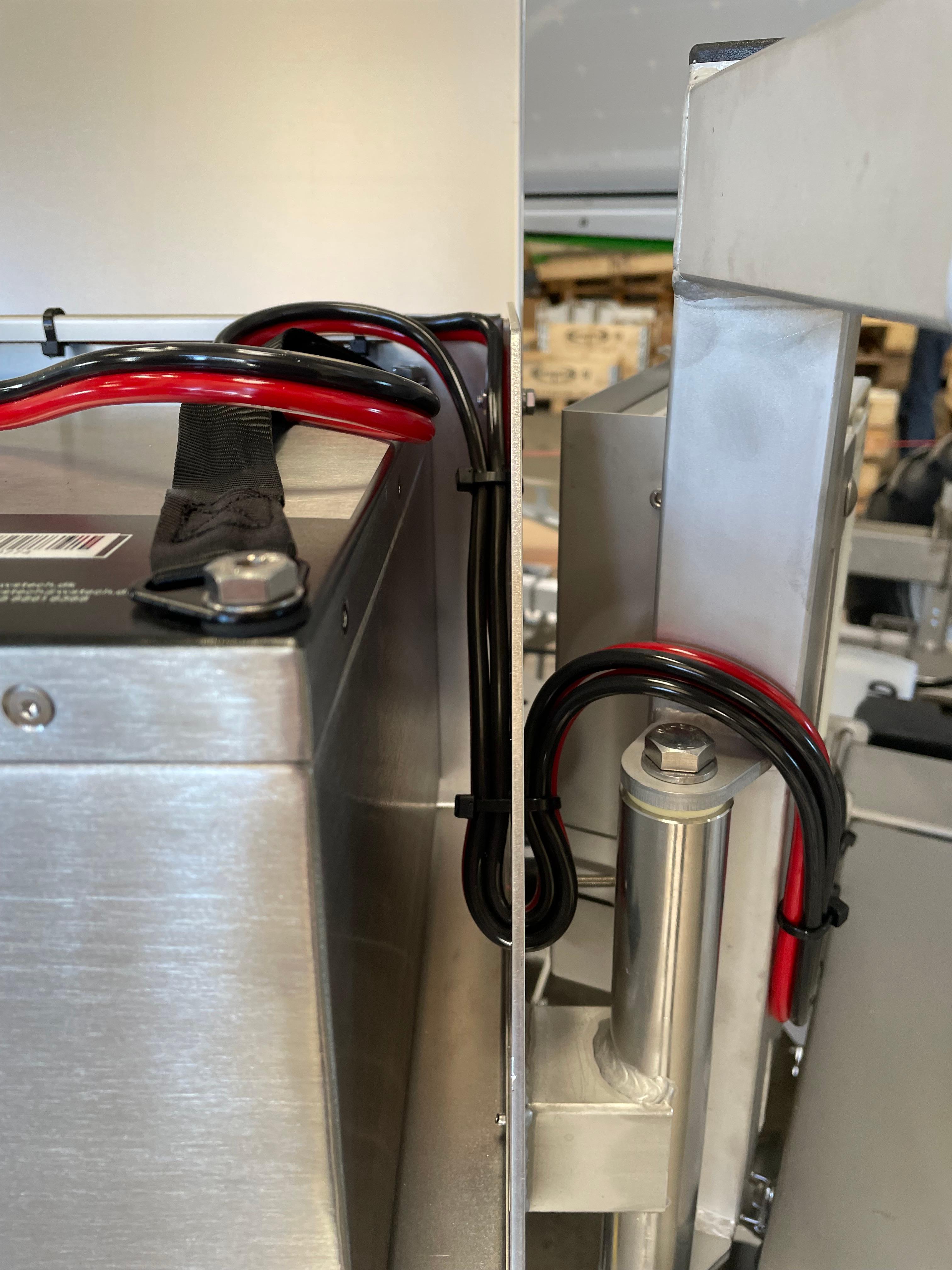
15) Have the electrical cable running from the power bank support, into the battery housing on the lower part of the robot. Make sure the cable is placed in the correct way as shown in the images
- PLEASE REFER TO THE FOLLOWING ARTICLE IF YOU ARE INSTALLING THE POWER BANK TO A 2021 OR 2020 ROBOT: Power bank - ELECTRICAL CONNECTIONS schemes
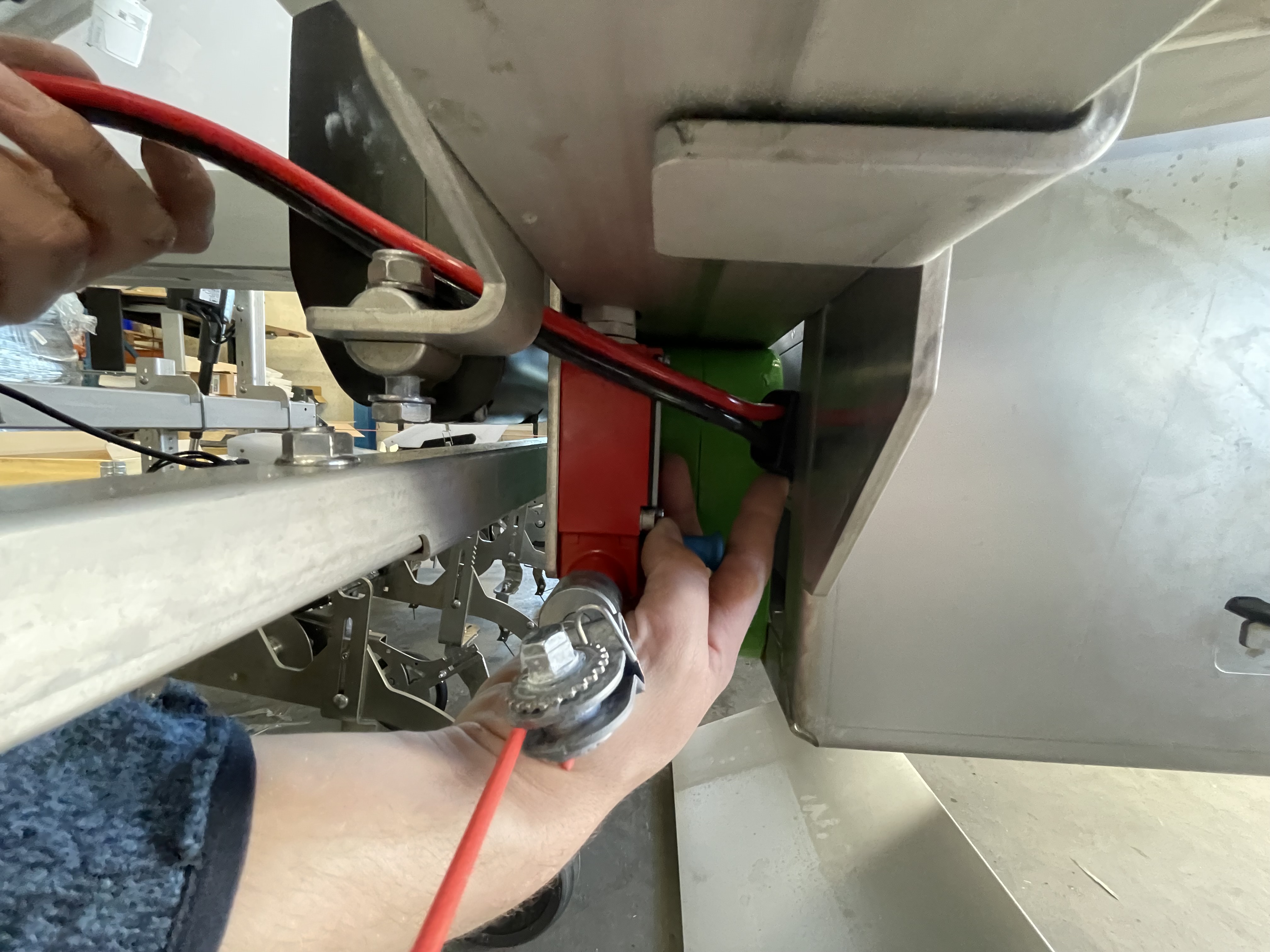
16) Have the cable passing between the actuator and the frame
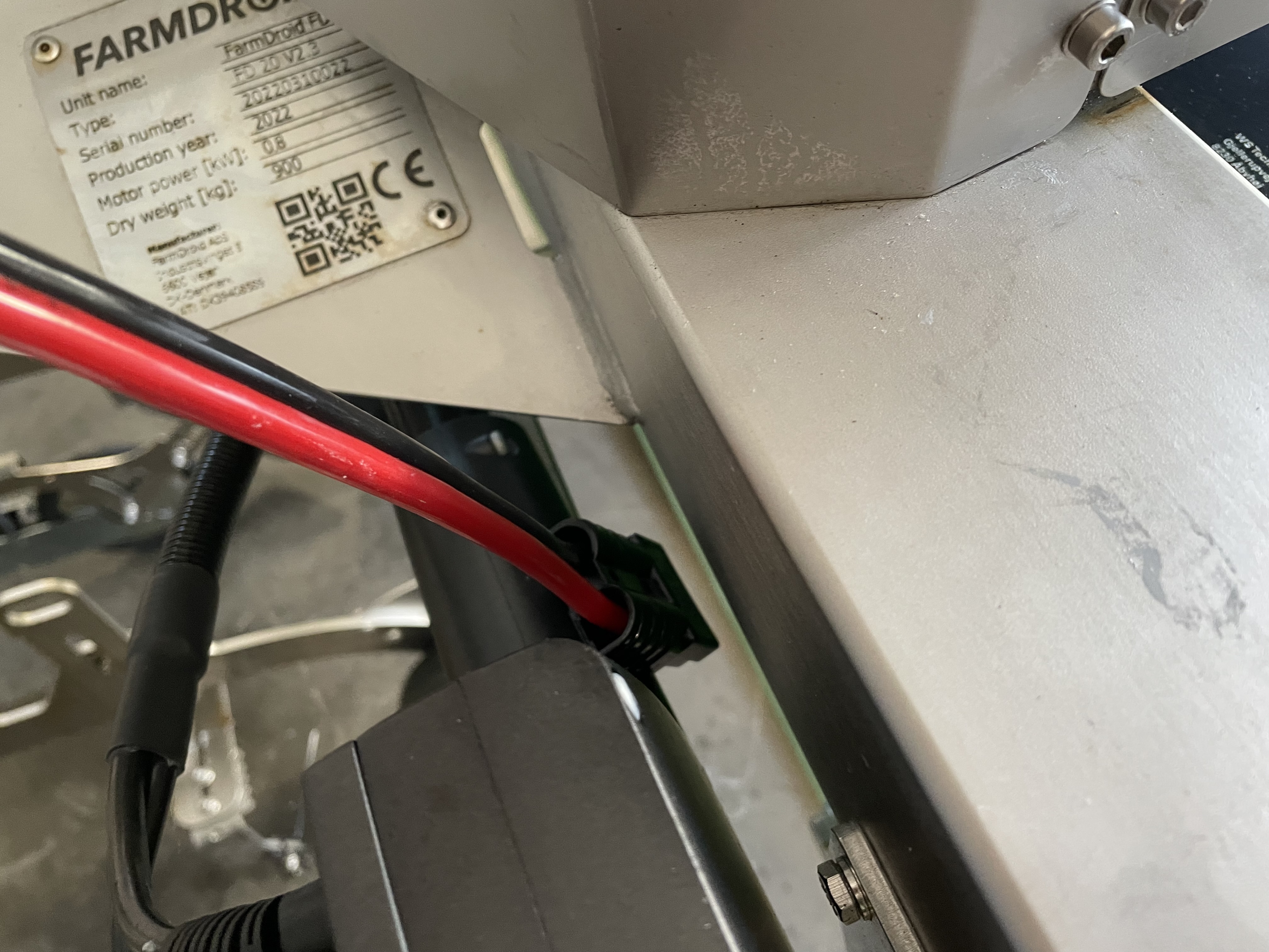
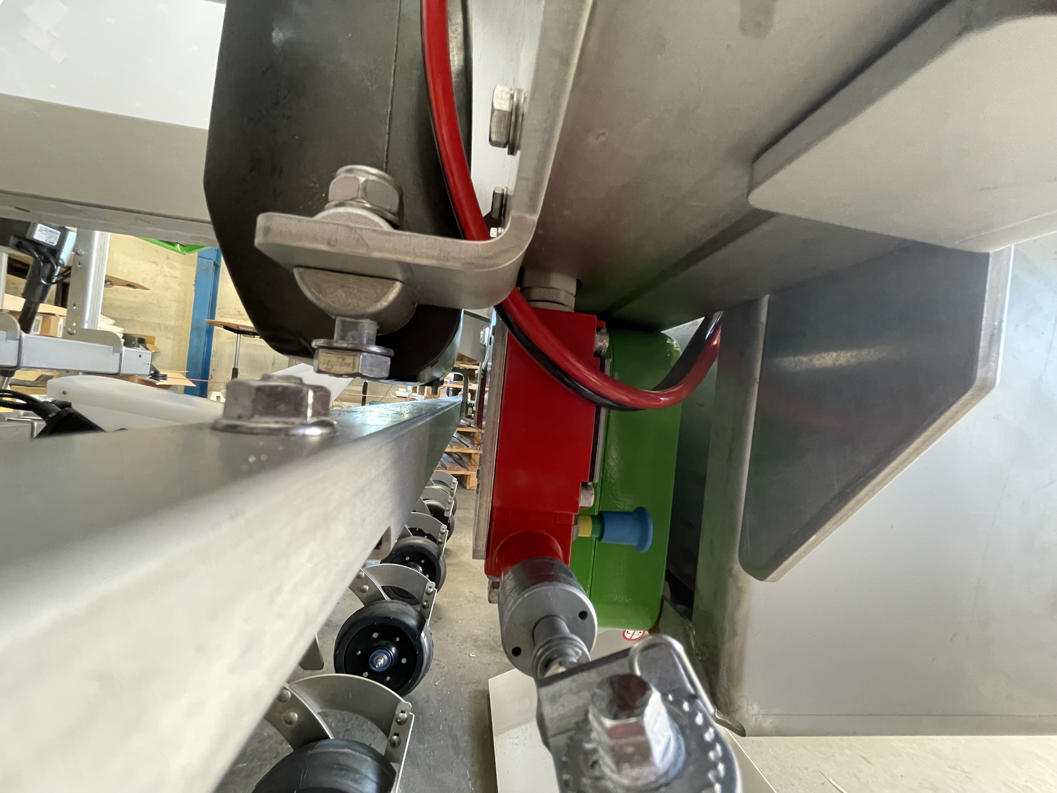
17) And finally have the cable coming out into the battery housing, below the electrical panel
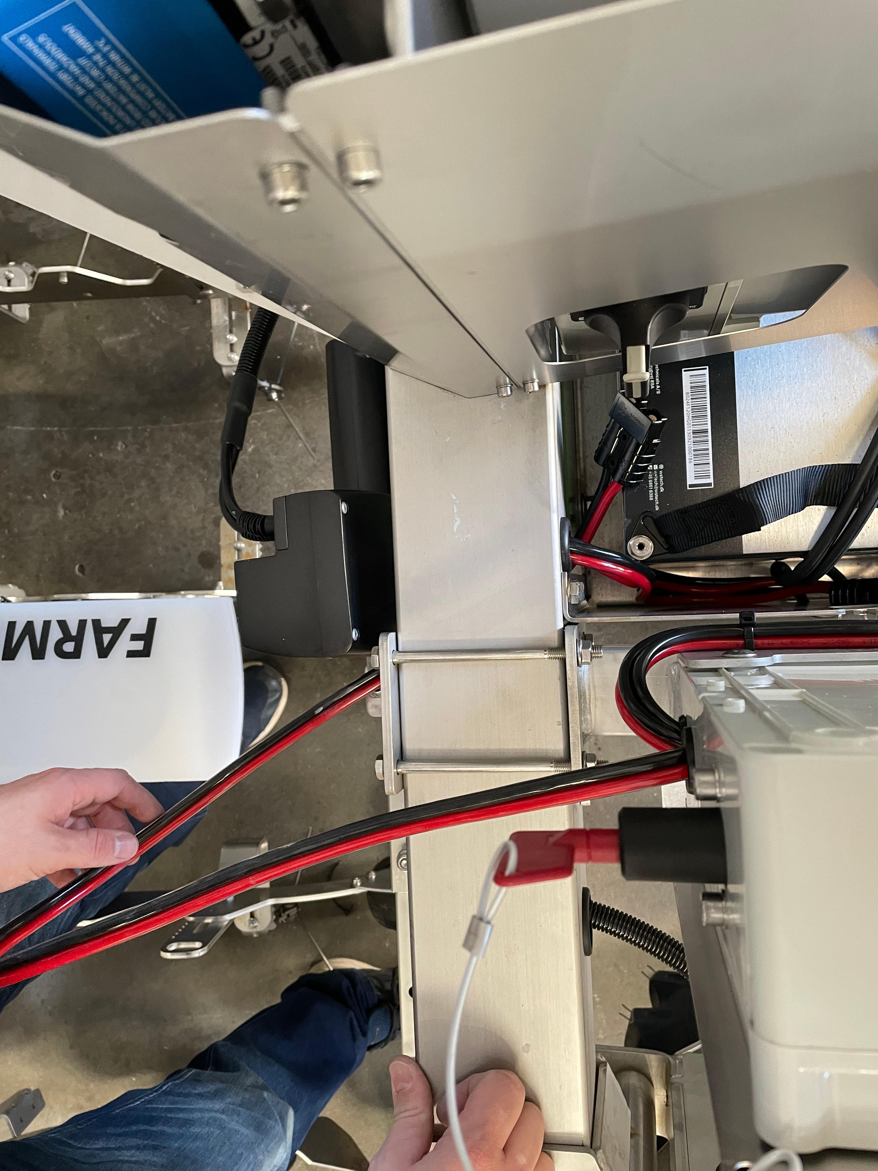
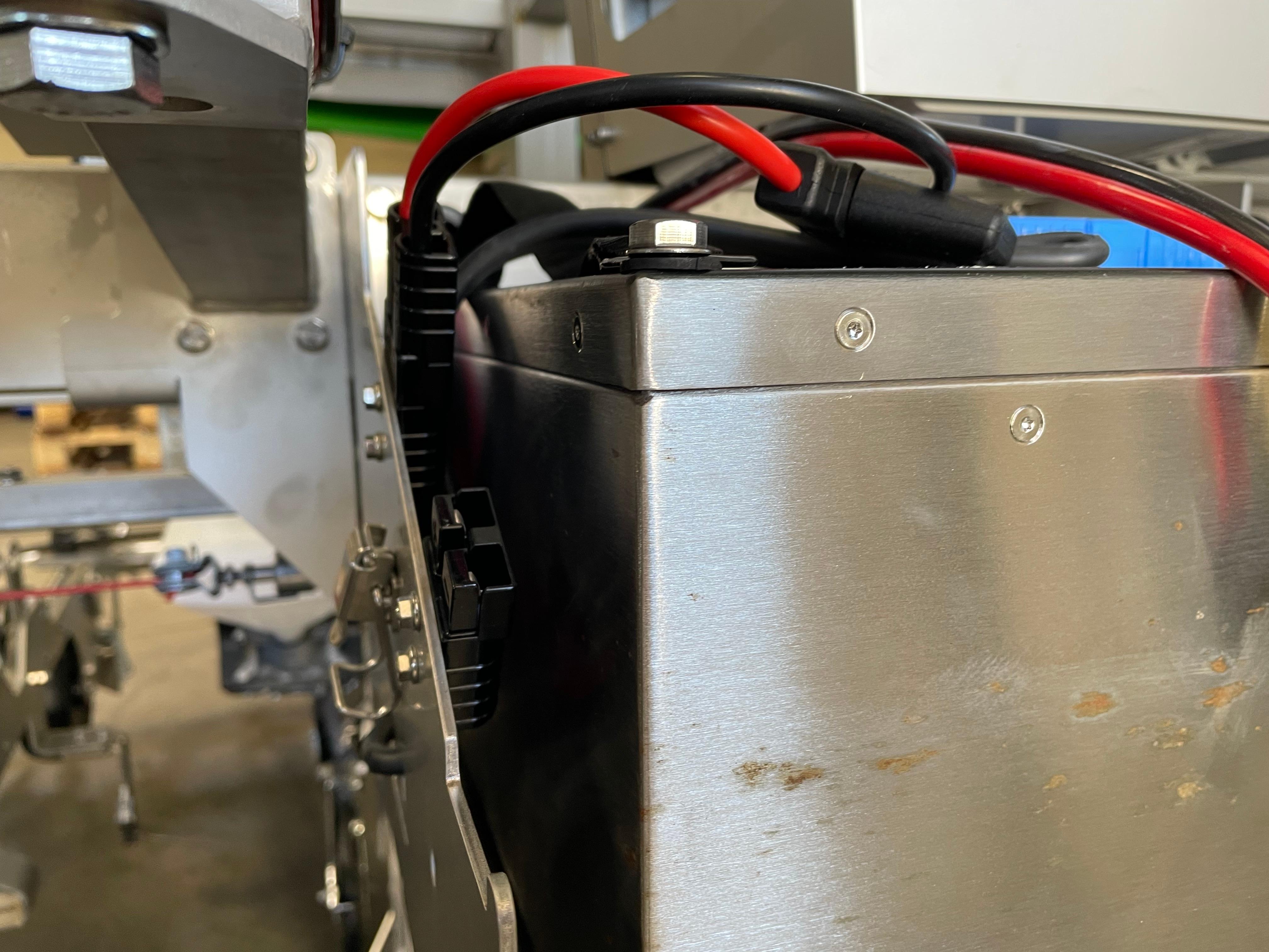
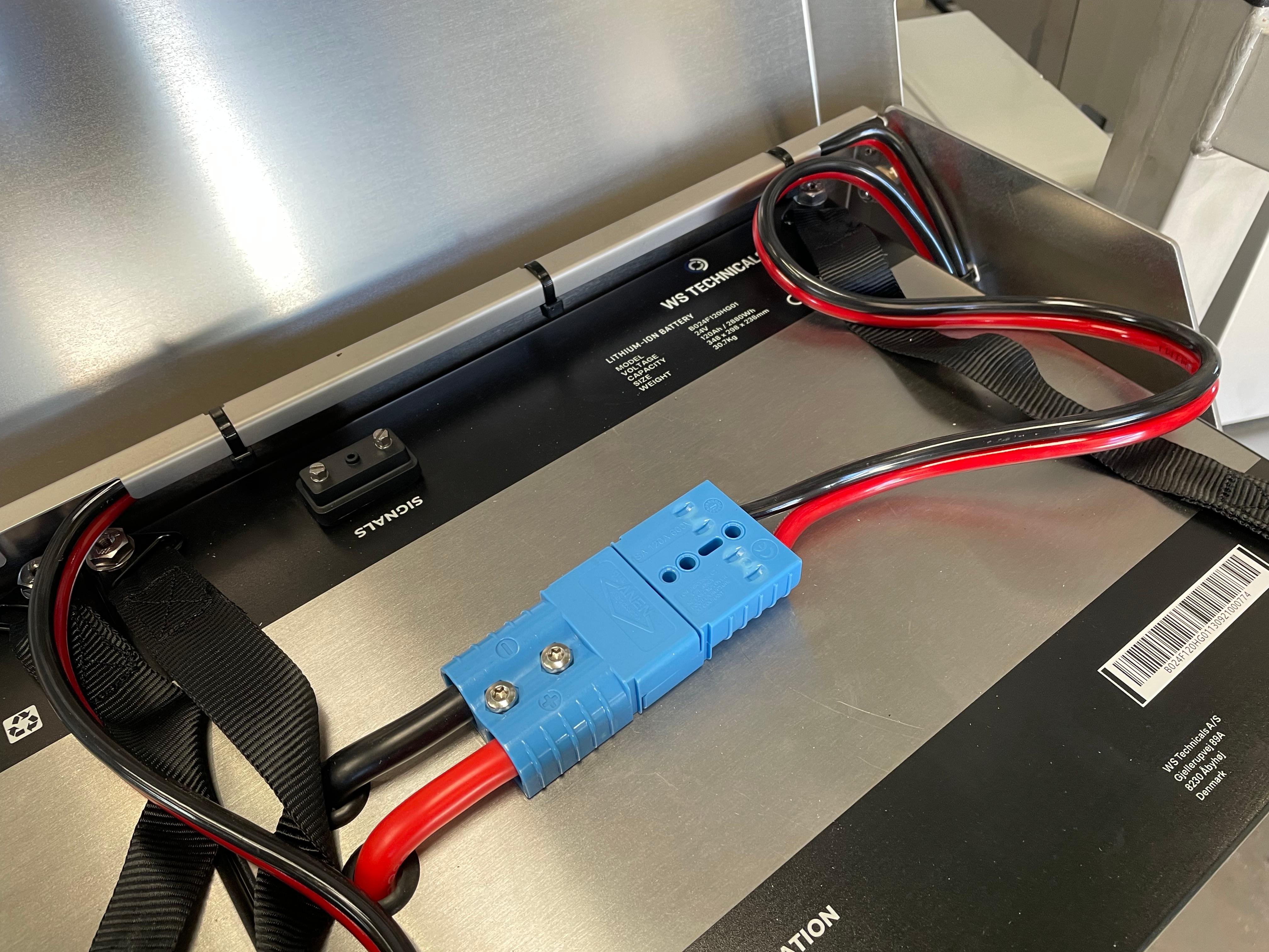
18) Plug in the cable on the available plug, placed in the left side of the battery housing
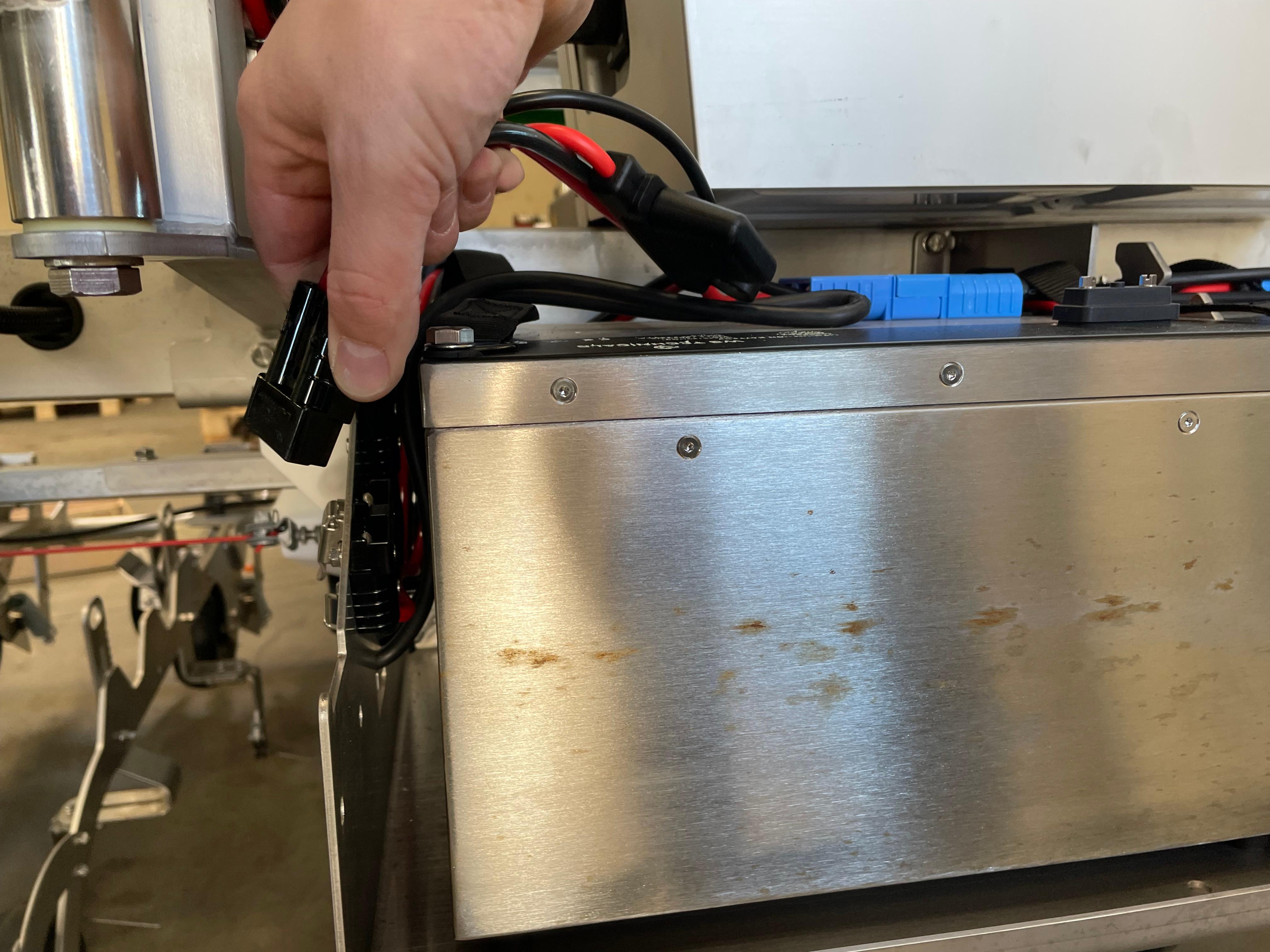
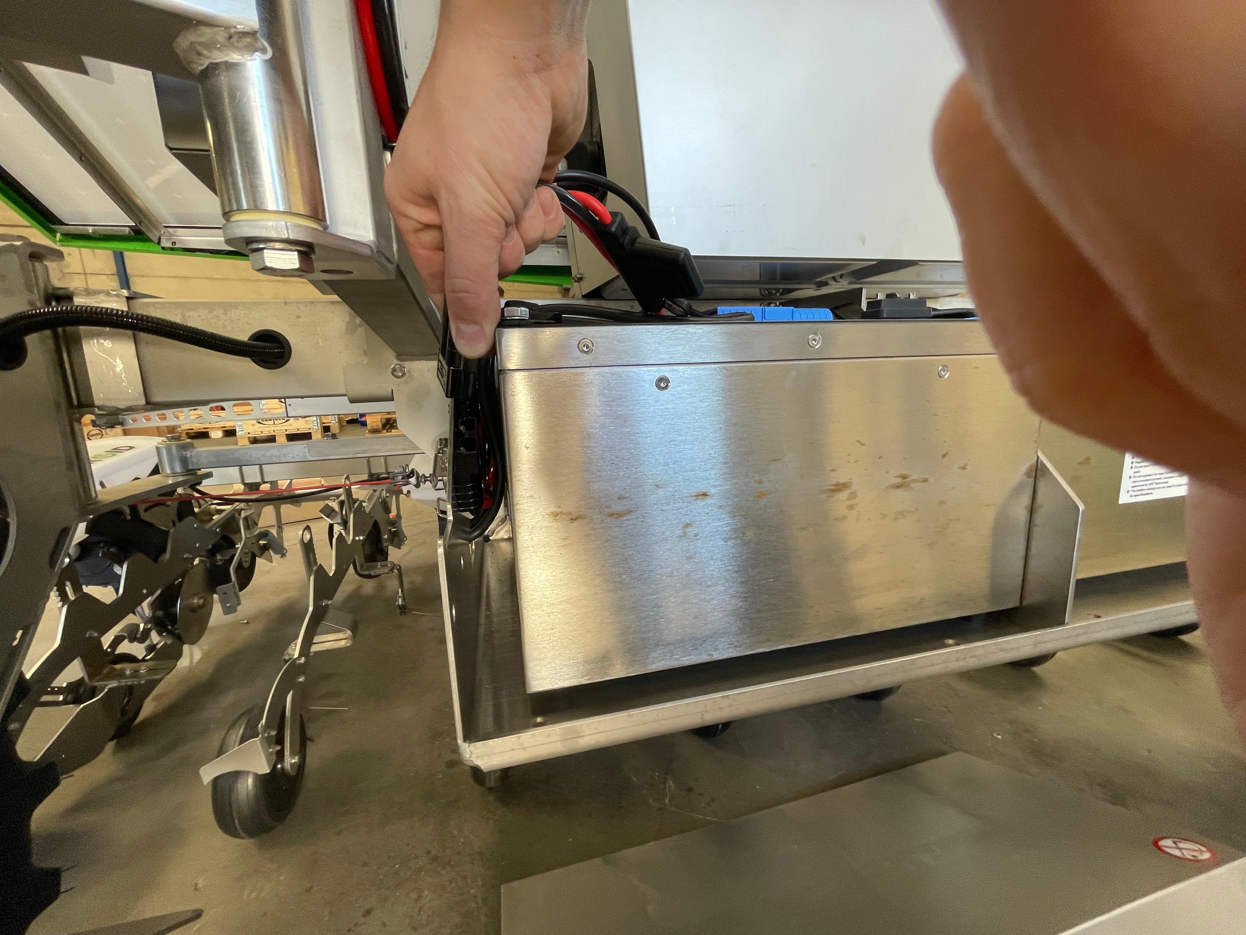
19) Swing the power bank case to close it
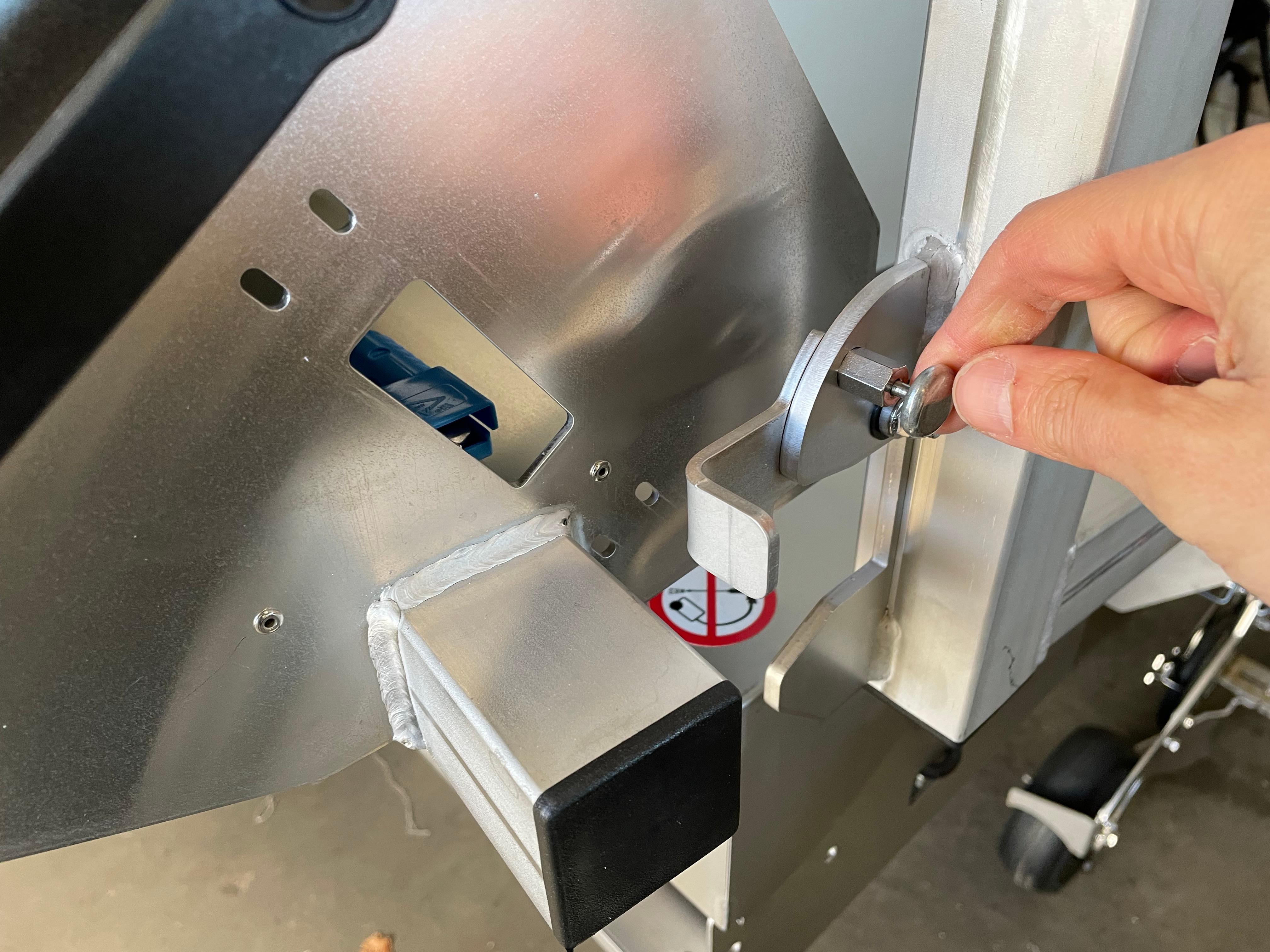
20) Then tighten the bolts on the other side. These bolts should be tighten only AFTER closing the power bank case, to make sure all components are aligned.
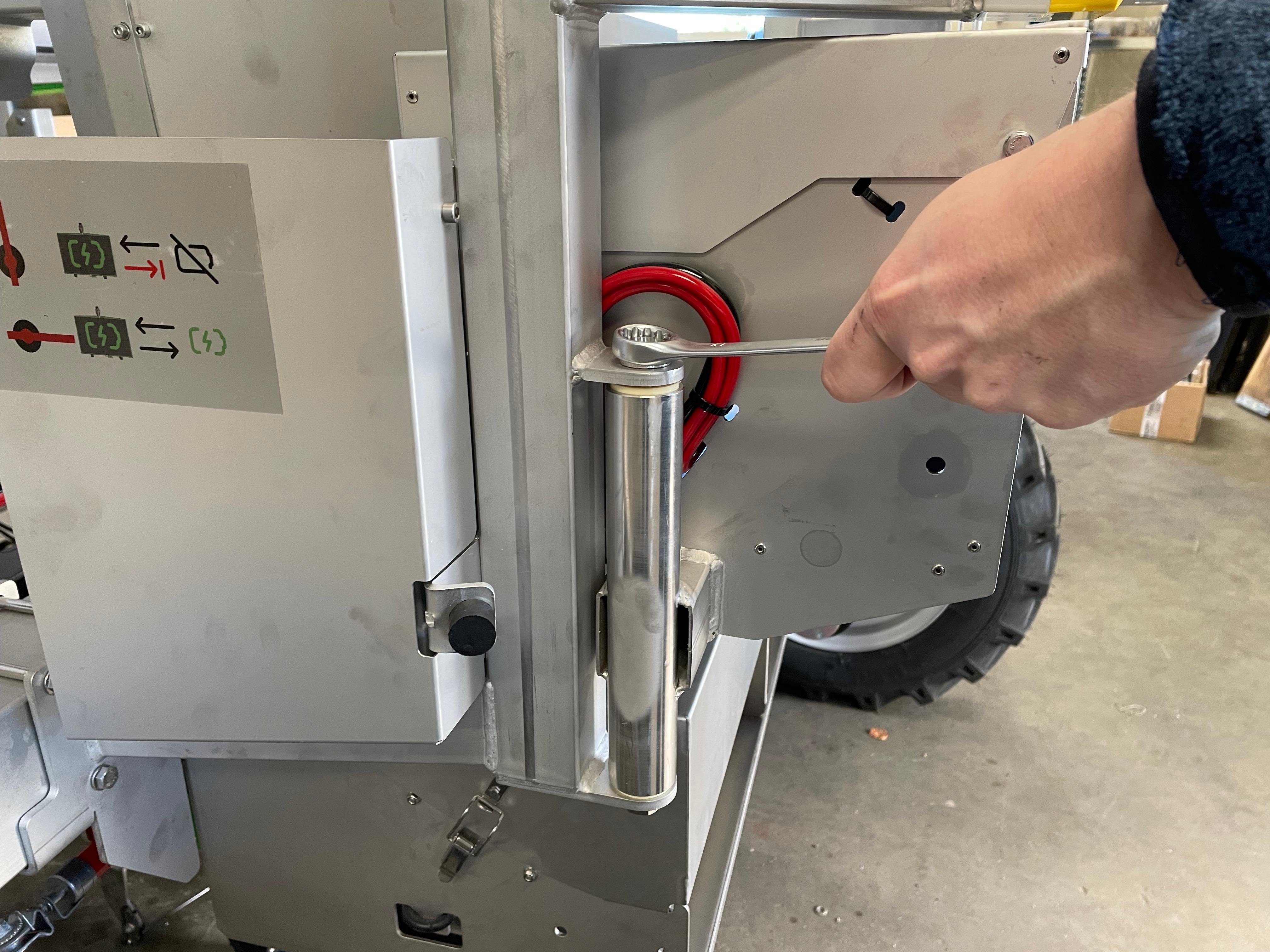
21) Now finish with the installation of the HMI by fixing it to the new bracket with a 10 mm wrench
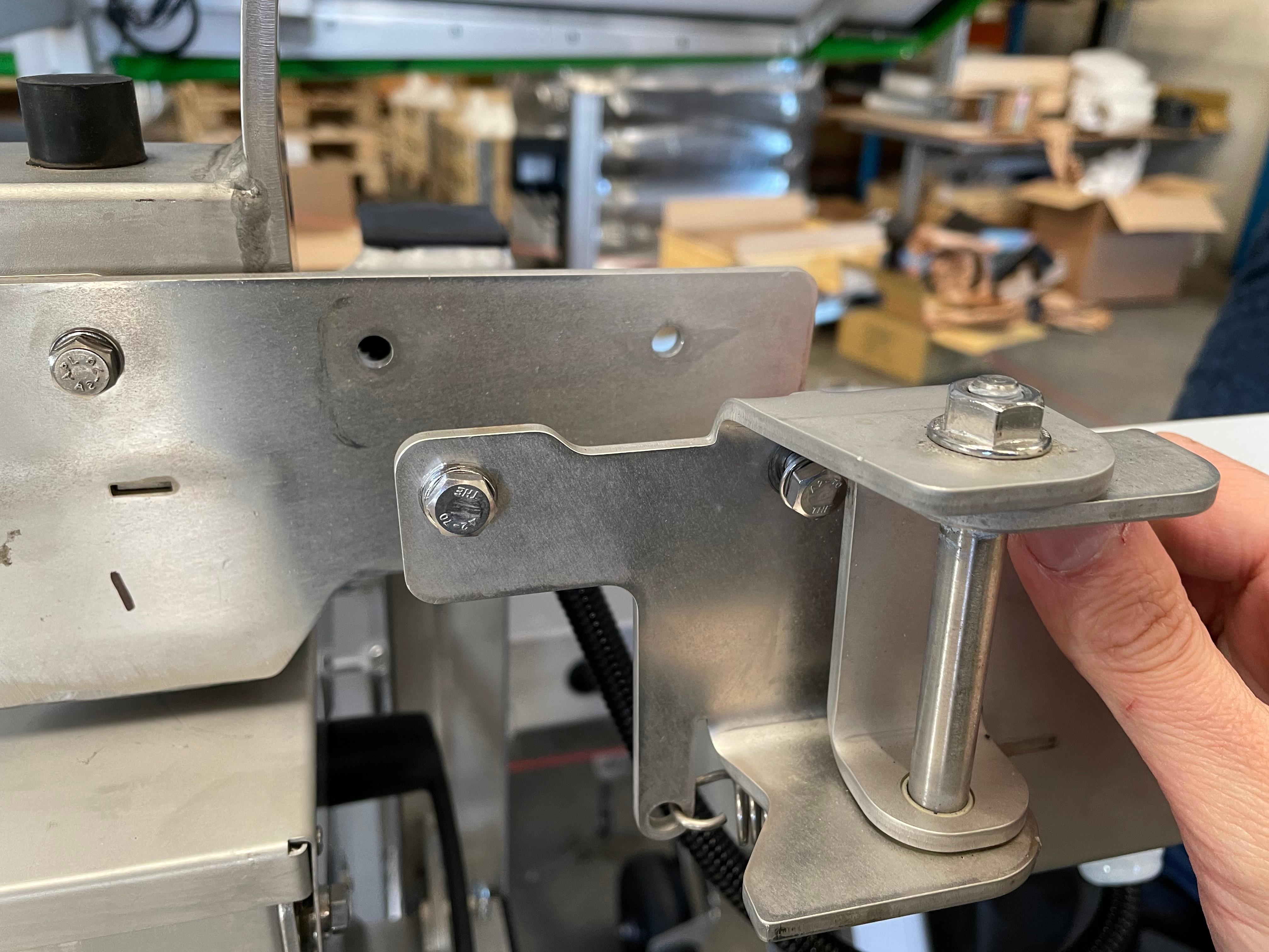
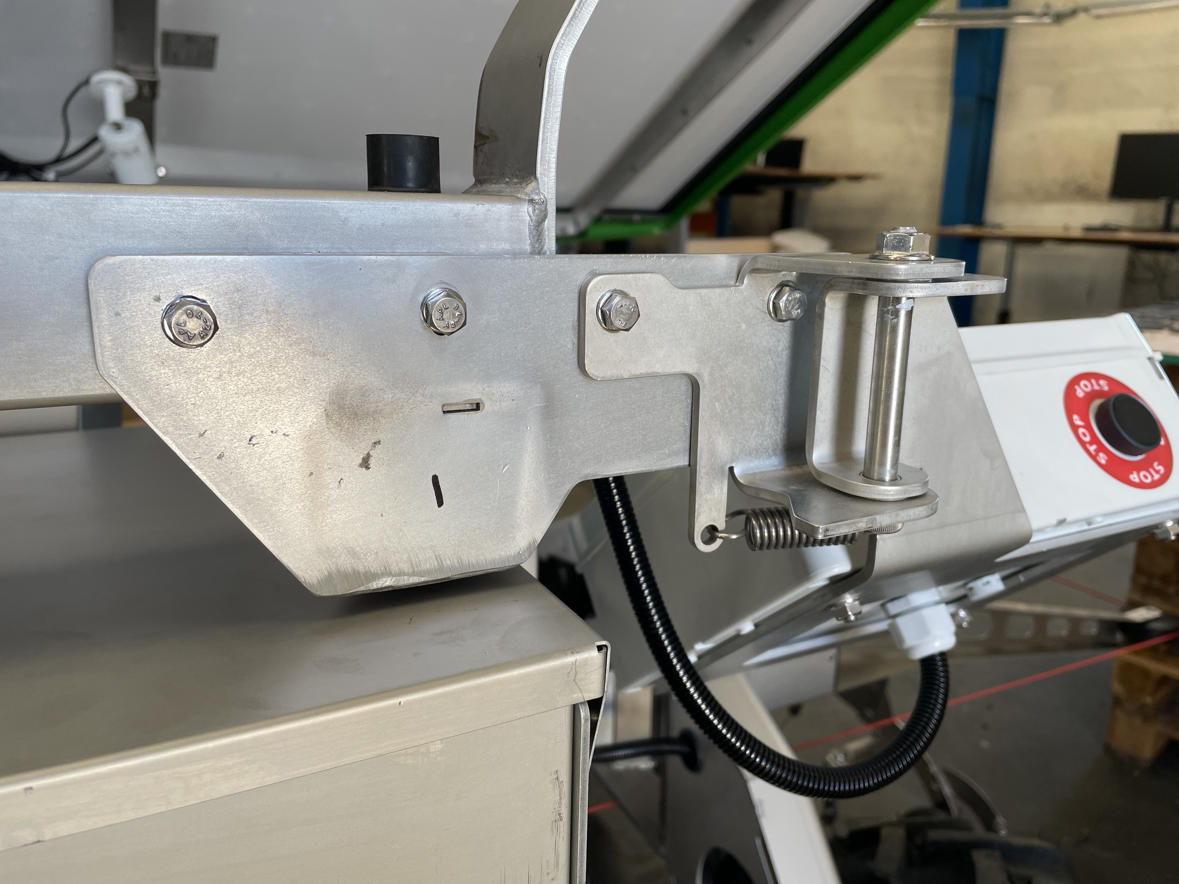
22) Secure the emergency stop button in place, first using the 3 mm Allen wrench, then with a screwdriver
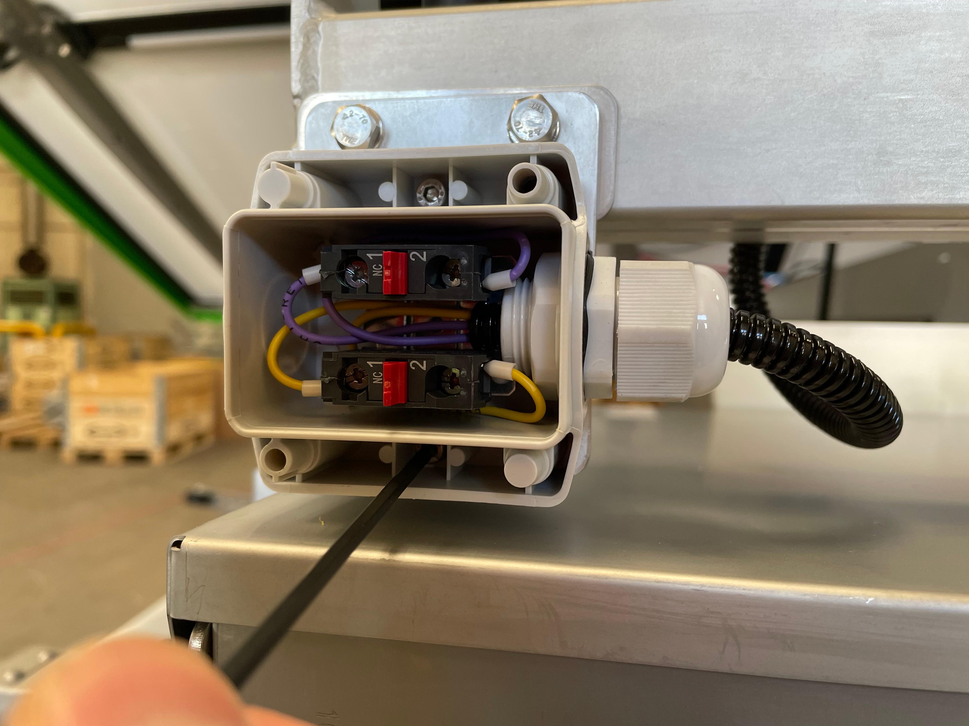
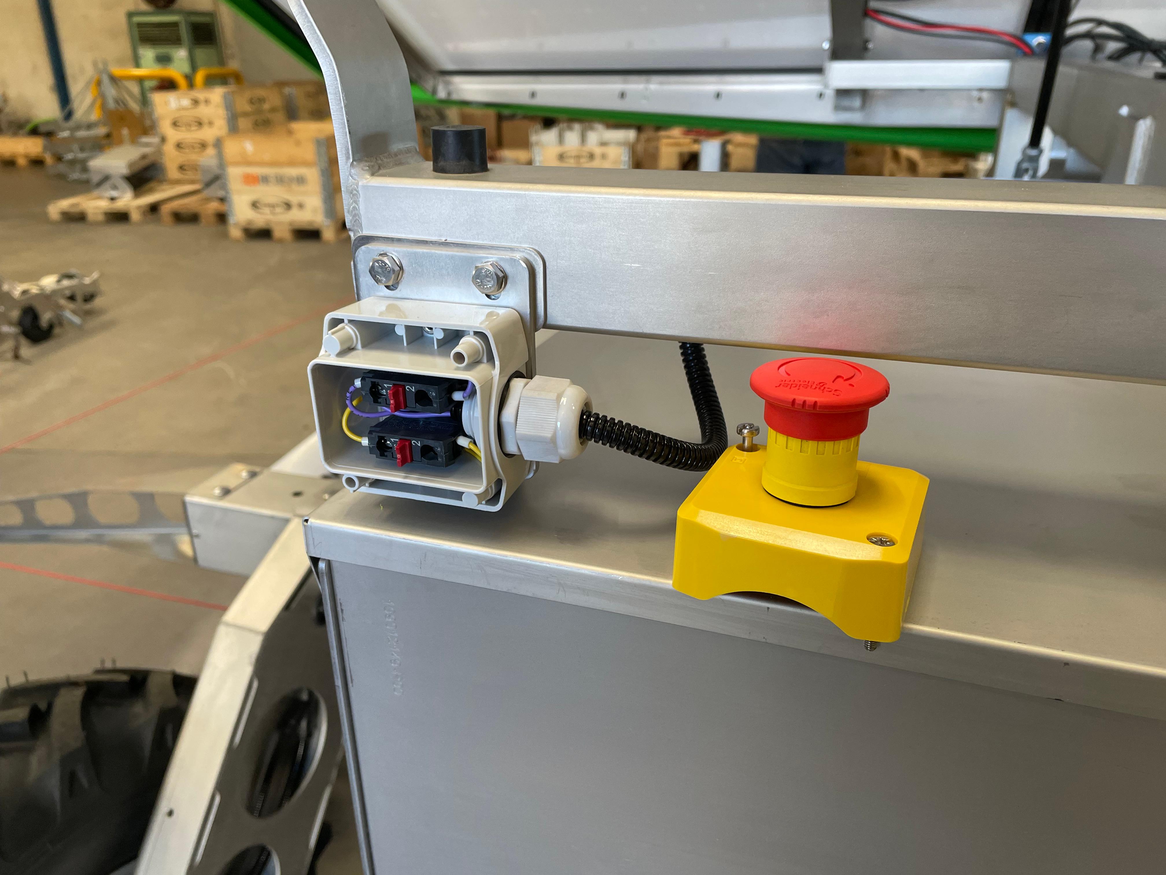
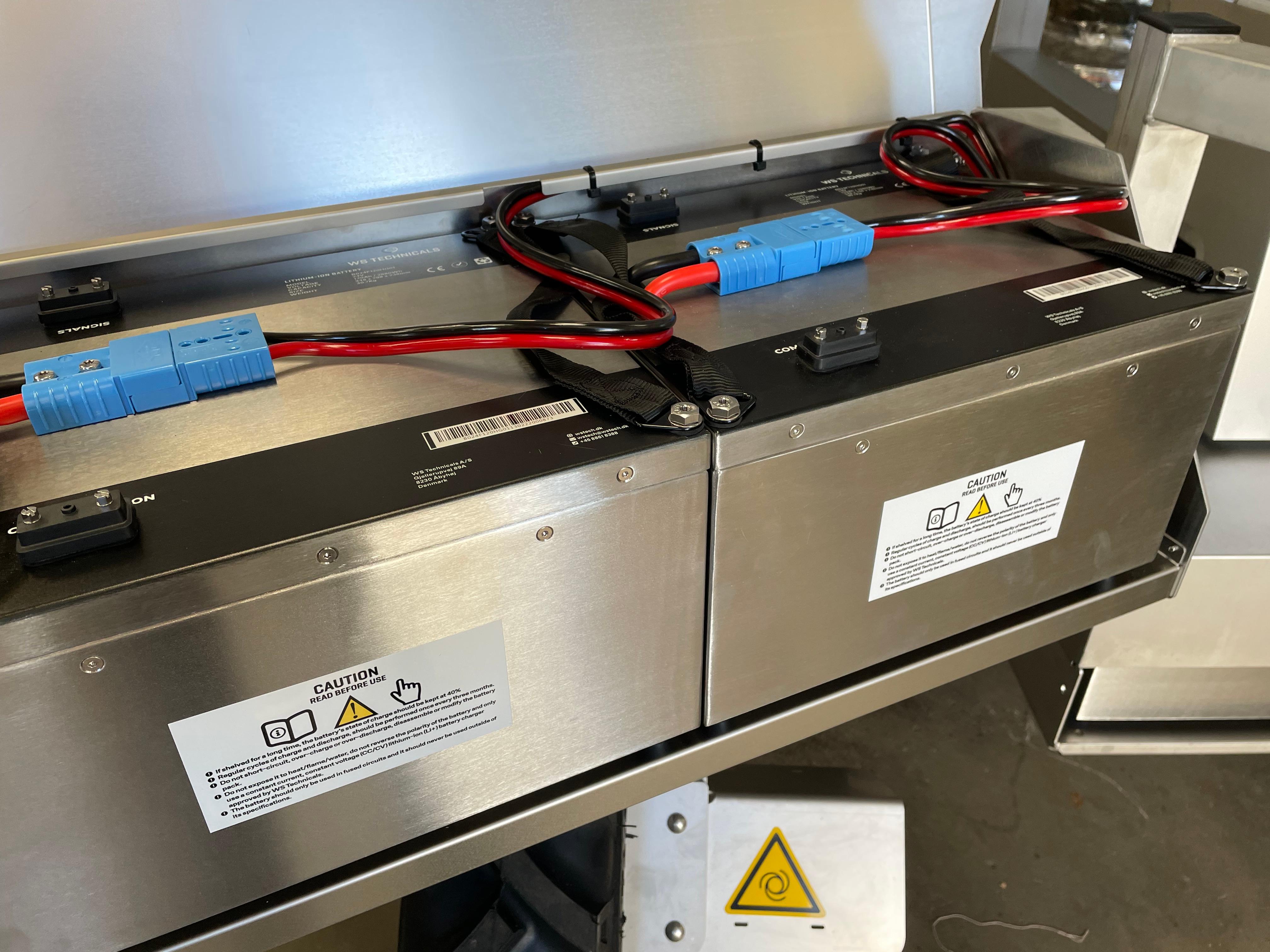
23) This is how a correct installation would look like. Please notice where the batteries cables are secured!
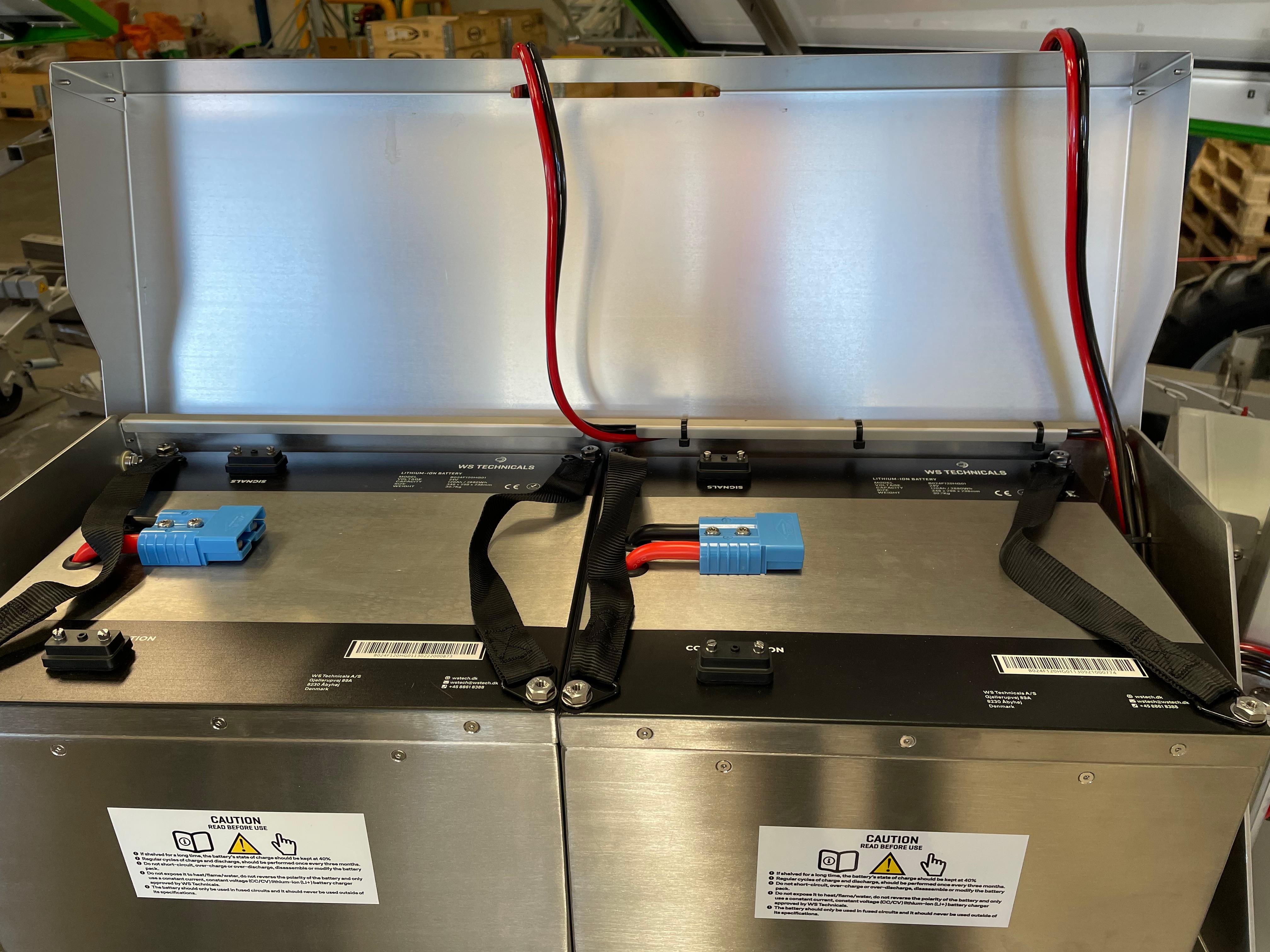
24) Place the batteries in the case and connect them to the robot
25) If all is done correctly, then you would have only these 3 brackets left
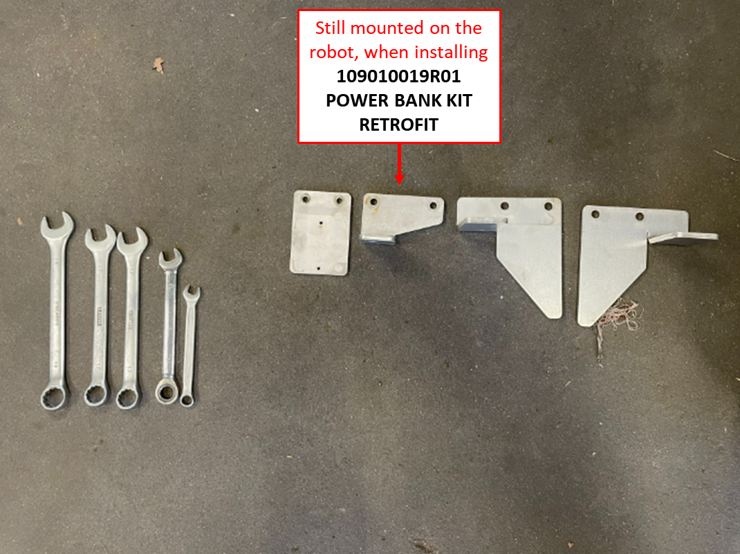
26) The installation is now finished and you can enjoy your robot with extended autonomy!
